Arrangement method and structure of power assembly for long-wheelbase four-wheel-drive automobile
An automobile powertrain and four-wheel drive technology, which is applied in the direction of power devices, control devices, vehicle components, etc., can solve the problem of large dynamic load bending moment, large alternating load stress range, and dynamic Assembly vibration and other problems, to achieve the effect of reducing dynamic load bending moment and alternating variable load stress amplitude, reducing alternating variable load stress, and reducing dynamic load bending moment
- Summary
- Abstract
- Description
- Claims
- Application Information
AI Technical Summary
Problems solved by technology
Method used
Image
Examples
Embodiment 1
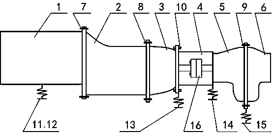
[0027] Such as figure 1 , 3 shown.
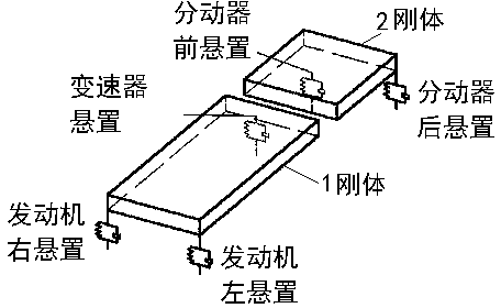
[0028] A powertrain arrangement method for a long-wheelbase four-wheel-drive vehicle. First, the engine casing with the engine mounted thereon is suspended on the vehicle frame through at least two points, and the two suspension points should be symmetrically distributed on both sides of the casing. At the same time, rigidly connect the engine casing to the front casing of the transmission, and rigidly connect the rear casing to the front casing of the transmission; secondly, suspend the transmission rigidly connected to the front and rear casings on the frame; thirdly, connect the rear casing of the transmission Flexible connection directly with the front case of the transfer case (a flexible connection can be formed by adding a rubber elastic bushing between the bolt and the mounting hole or other conventional connection methods, this connection method is actually a semi-rigid and semi-flexible connection ), and suspend the front case ...
Embodiment 2
[0030] Such as figure 1 , 3 shown.
[0031] A long-wheelbase four-wheel-drive vehicle powertrain layout structure, which includes an engine housing 1 with an engine installed, a transmission front housing 2 and a transmission rear housing 3, and a transfer case front housing with a transition plate 4 installed. Case 5 and transfer case rear case 6. The engine case 1 is suspended on the vehicle frame at least through two suspension points symmetrically arranged on both sides of the engine case. The engine case 1 and the front case 2 of the transmission One end is rigidly connected by a bolt 7, and the other end of the transmission front case 2 and one end of the transmission rear case 3 are rigidly connected by a bolt 8. After the rigid connection, the transmission front case 2 and the transmission rear case 3 are suspended on a suspension of the vehicle frame. point (finally located at one end close to the front case 5 of the transfer case, such as figure 1 ), at least tw...
PUM
 Abstract
Description
Claims
Application Information
 - R&D Engineer
- R&D Manager
- IP Professional
- Industry Leading Data Capabilities
- Powerful AI technology
- Patent DNA Extraction
Browse by: Latest US Patents, China's latest patents, Technical Efficacy Thesaurus, Application Domain, Technology Topic, Popular Technical Reports.
© 2024 PatSnap. All rights reserved.Legal|Privacy policy|Modern Slavery Act Transparency Statement|Sitemap|About US| Contact US: help@patsnap.com


