
Four-wheel independent suspension system of electric wheelchair

An electric wheelchair and frame technology, which is applied to the rescue of vehicles, patient chairs or special transportation tools, medical transportation, etc., can solve the problems of miniaturization and compactness of electric wheelchairs, and the shock absorption effect of spring structure is not very good. , the complex structure of spring shock absorption, etc., to achieve the effect of obvious shock absorption, comprehensive shock absorption, and small space.

Active Publication Date: 2016-04-20
JIANGMEN CHAOYANG PRECISION MFG
View PDF6 Cites 0 Cited by
  • Summary
  • Abstract
  • Description
  • Claims
  • Application Information

AI Technical Summary

Problems solved by technology

However, the driving road of electric wheelchairs is not completely flat without bumps. Driving electric wheelchairs on uneven roads with pits will bring a lot of vibration. In order to improve driving comfort, a shock absorbing mechanism must be installed to achieve The purpose of shock absorption
The shock absorption in the traditional technology is usually realized by using a spring structure between the seat cushion and the vehicle frame, but the shock absorption effect of the spring structure is not very good, and its shock absorption effect is generally limited to a high degree of shock absorption. The structure of the shock is complex and the implementation cost is high. Because the spring occupies a certain height space, it is not conducive to the miniaturization and compactness of the electric wheelchair

Method used


Image

  • Four-wheel independent suspension system of electric wheelchair
  • Four-wheel independent suspension system of electric wheelchair
  • Four-wheel independent suspension system of electric wheelchair

Examples


Embodiment Construction

[0023] The present invention will be further described in detail below with reference to the drawings and embodiments.

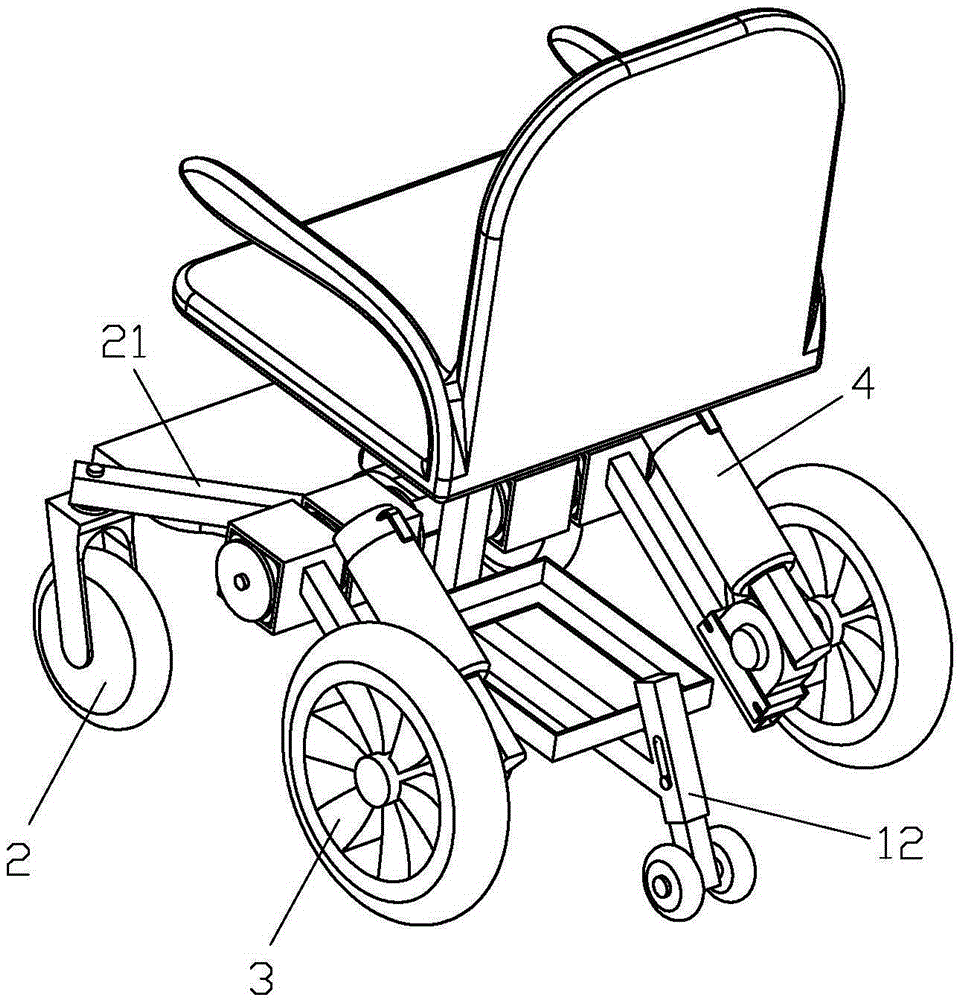
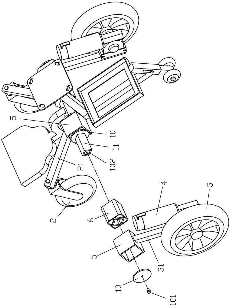
[0024] Reference Figure 1 ~ Figure 12 , The four-wheel independent suspension system of the electric wheelchair of the present invention includes a frame 1, two front wheels 2 and two rear wheels 3, each of the front wheels 2 and the rear wheels 3 is hinged on its respective front link 21 And the rear link 31, where the front wheel 2 passes such as Picture 12 The connecting rod 22 shown is connected to the front connecting rod 21, and the top end of the connecting rod 22 is a threaded section 23. The threaded section 23 passes through the through hole 24 on the front connecting rod 21 and is locked and fixed by a nut 25 to reduce rotation. Friction, a bearing 26 is provided between the hole wall of 24 and the threaded section 23; each rear connecting rod 31 is provided with a corresponding motor 4, and the motor 4 can be used as figure 1 The motor shown in the...


PUM


Abstract

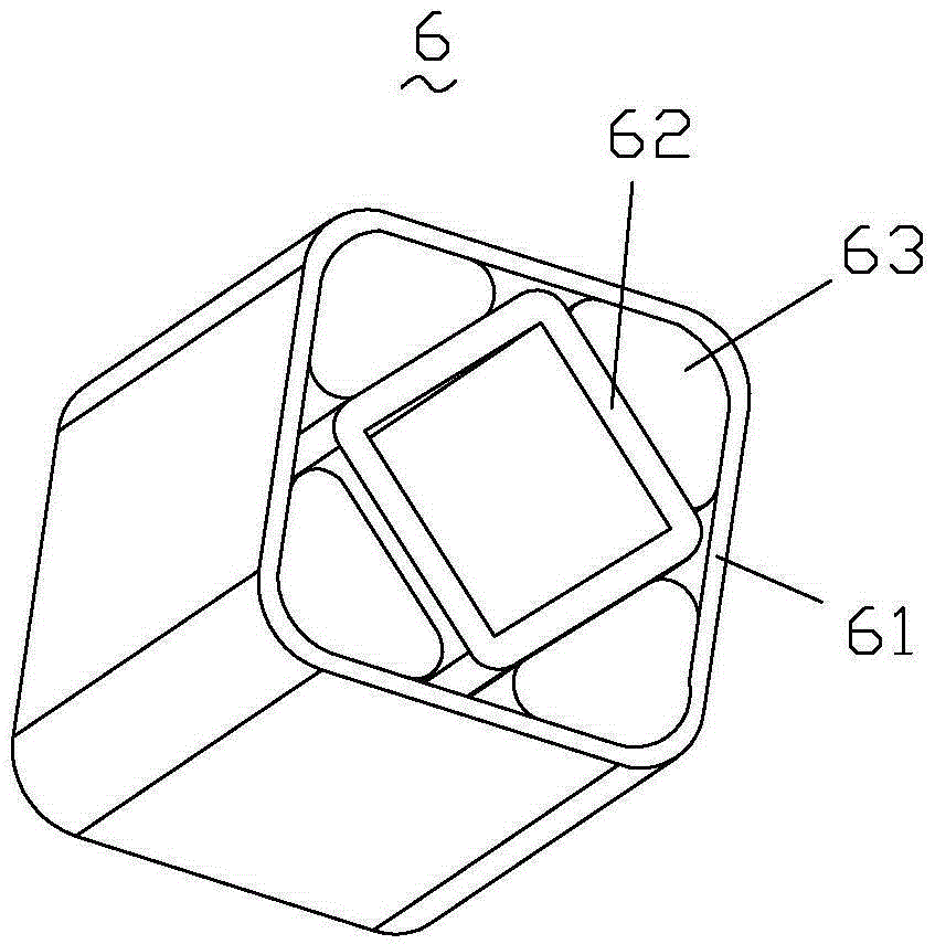
The invention discloses a four-wheel independent suspension system of power-driven wheelchairs. The four-wheel independent suspension system comprises a frame, two front wheels and two back wheels. Each of the front wheels and each of the back wheels are hinged on each of front connecting rods and back connecting rods respectively, a cross rod extending in vehicle width direction is arranged on the frame, adapter sleeves in box section structure are arranged at end portion of the front connecting rods and the back connecting rods, and shock absorbers are sleeved in the adapter sleeves. Each of the shock absorbers comprises a rectangular outer tube and a rectangular inner tube, the inner tube is arranged in the outer tube and can rotate 45 degrees opposite to the outer tube, seamed edge of the inner tube is opposite to the tube wall of the outer tube, and an elastic rubber mat is arranged between the seamed edge of the outer tube and the tube wall of the inner tube; inner tubes of the chock absorbers are sleeved on the cross rod, the front wheels and the back wheels are respectively and independently suspended on the frame via the adapter sleeves and the shock absorbers. The four-wheel independent suspension system of the power-driven wheelchairs is good in shock absorbing effect, comprehensive in shock absorbing direction and is beneficial to the miniaturization and compactness of the power-driven wheelchairs.

Description

Technical field [0001] The invention relates to an electric wheelchair, in particular to a four-wheel independent suspension system of the electric wheelchair. Background technique [0002] The electric wheelchair is based on the traditional manual wheelchair, superimposed on the high-performance power drive device, intelligent control device, battery and other components to transform and upgrade. It has a manual operation intelligent controller. Nowadays, the electric wheelchair has become the elderly with limited mobility. , An indispensable means of transportation for the disabled. However, the driving road of an electric wheelchair is not completely smooth or rugged. Driving an electric wheelchair on uneven roads with pits will cause great vibration. In order to improve the driving comfort, a shock absorption mechanism must be installed to achieve this. The purpose of cushioning. The shock absorption in the traditional technology is usually realized by using a spring struct...

Claims


Application Information

Patent Timeline
Patent Type & Authority Patents(China)
IPC IPC(8): A61G5/10A61G5/04
Inventor 林崇传
Owner JIANGMEN CHAOYANG PRECISION MFG
Learn More