Cable system fault positioning and load monitoring method

A technology for fault location and load monitoring, which is applied in the direction of fault location, measurement of electricity, and measurement of electrical variables. It can solve the problems of modifying parameters, poor real-time performance of load monitoring, and low efficiency, so as to improve efficiency and accuracy, ensure real-time performance, cost reduction effect

Inactive Publication Date: 2013-12-11
BEIJING HAORUIDA TECH
View PDF5 Cites 16 Cited by
  • Summary
  • Abstract
  • Description
  • Claims
  • Application Information

AI Technical Summary

Problems solved by technology

However, the detection unit and trigger unit of the traditional fault indicator are built by analog circuits, and the parameters for judging whether the line is faulty are fixed, and the parameters cannot be modified according to the operation conditions of different lines on site. Interactivity is not easy to achieve. Data accuracy and fault false alarm rate are not easy to control, so the current fault location and load monitoring system has the following problems: (1) Line information adopts distributed collection and distributed processing, which is efficient and low cost; (2) Fault indicators Limited by power consumption, high sampling frequency cannot be used, and load current cannot be sent frequently, so the real-time performance of load monitoring is poor; (3) Since the fault detection circuit is separated from the load current detection circuit, the magnitude of the fault current It cannot be detected, and when a fault occurs, the fault current cannot be sent; (4) The fault indicator can only be sampled and judged by the analog circuit, and the limit value and time limit of the fault alarm cannot be set according to the actual situation on site; (5) Cannot distinguish between permanent faults and transient faults
These problems have seriously affected the cable system line grounding short circuit fault location and the effect of load monitoring

Method used


Image

  • Cable system fault positioning and load monitoring method
  • Cable system fault positioning and load monitoring method

Examples


Embodiment Construction

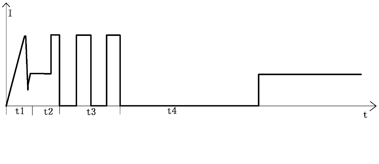
[0021] Such as figure 1 As shown, in the present invention, the three-phase ABC and zero sequence of the power cable 1 are respectively clamped to measure CT2, sense the current on the primary side, and perform the transformation ratio.

[0022] In the fault indication terminal 3, the short-circuit fault judgment value and the ground fault judgment value are preset; the short-circuit fault judgment value and the ground fault judgment value can be adjusted at any time according to site needs.

[0023] The fault indication terminal 3 uses 1ms as the cycle to sense and sample the primary side current AD of the measurement CT (primary side current transformer) mounted on the ABC three-phase and zero-sequence, and sample 20 points per cycle. And calculate the current effective value of each cycle.

[0024] The fault indication terminal performs fault judgment based on the sampled current value.

[0025] The judgment of short circuit and ground fault in the present invention is based on the...


PUM


Abstract

The invention relates to a cable system fault positioning and load monitoring method. The method includes the steps of firstly, arranging measurement CTs on an A phase of a power cable, a B phase of the power cable, a C phase of the power cable and a zero sequence of the power cable in a clamped mode respectively, sensing the current on the primary side and conducting transformation; secondly, presetting a short trouble judgment value and an earth fault judgment value at a fault indication terminal; thirdly, sampling the current AD sensed through the CTs and transformed on the primary side through the fault indication terminal by taking 1ms as a period, sampling 20 points in each cyclic wave, and calculating the current effective value in each cyclic wave; fourthly, comparing the sampled current effective value of the A phase, the sampled current effective value of the B phase and the sampled current effective value of the C phase in the current cyclic wave with the current effective value in the first previous cycle and the current effective value in the second previous cycle, and judging that the short trouble occurs when one of the two differential values or both the two differential values are larger than the preset value; fifthly, comparing the zero sequence current effectively value in each sampled cyclic wave with the preset earth fault judgment value, and judging that the earth fault occurs when the zero sequence current effectively values are larger than the earth fault judgment value.

Description

Technical field [0001] The invention relates to a grounding short-circuit fault location and load monitoring method of cable system lines in the power industry, which can replace the traditional fault location and load monitoring system composed of a fault indicator with the function of measuring current. Background technique [0002] Real-time monitoring of the ground short-circuit fault and load of the power cable system is the basic requirement for the realization of distribution network automation. In the existing power system cable line monitoring, traditional fault indicators and fault indication terminals are often used to form a fault location and load monitoring system. The fault indicator has a current measurement function, and is equipped with a detection circuit, a judgment circuit and a trigger unit. The fault indicator card is installed on the line and communicates with the fault indicator terminal interactively. When the fault indicator detects that there is faul...

Claims


Application Information

Patent Timeline
Patent Type & Authority Applications(China)
IPC IPC(8): G01R31/02G01R31/08
Inventor 薛兆春
Owner BEIJING HAORUIDA TECH
Why Eureka
Try Eureka