
Quick-opening manhole

A technology for quickly opening manholes and manhole covers, which is applied in biochemical instruments, biochemical equipment and methods, enzymology/microbiology devices, etc. Problems such as collision head or manhole takeover

Active Publication Date: 2013-12-11
江阴德尔热能机械有限公司
View PDF3 Cites 3 Cited by
  • Summary
  • Abstract
  • Description
  • Claims
  • Application Information

AI Technical Summary

Problems solved by technology

[0002] There is a manhole device on the top head of each fermenter, which is used as a channel for internal stirring installation, maintenance, and fermentation process to enter and exit the fermenter. In the existing fermenter manholes, the following generally exist Disadvantages: After using for a period of time, the fixing seat of the falling bolt and the lateral fixed shaft pin or bolt are both subjected to the torque when tightening and loosening, and at the same time, they are distorted and deformed by tension such as bolt pre-tightening and sealing pressure, so they cannot be turned over or even cannot be turned over. In normal use, the fixed seat welded on the manhole barrel section is subjected to the same torque and tension to deform the barrel section and make the seal invalid. The strength and rigidity of the manhole cover locking are insufficient. This form of manhole locking During the processing of the falling bolt, defects such as welding deformation often occur, and the turning angle is infinite. When opening, it often hits the head or the manhole connection, which seriously damages the surface or thread of the container.
The lifting device of the manhole cover uses thread or pitch to realize lifting by turning the handwheel or handle. For larger manholes, the operation is inconvenient and not flexible enough, the operation is cumbersome, and sometimes even difficult to operate and there are safety hazards

Method used


Image

  • Quick-opening manhole
  • Quick-opening manhole
  • Quick-opening manhole

Examples


Embodiment Construction

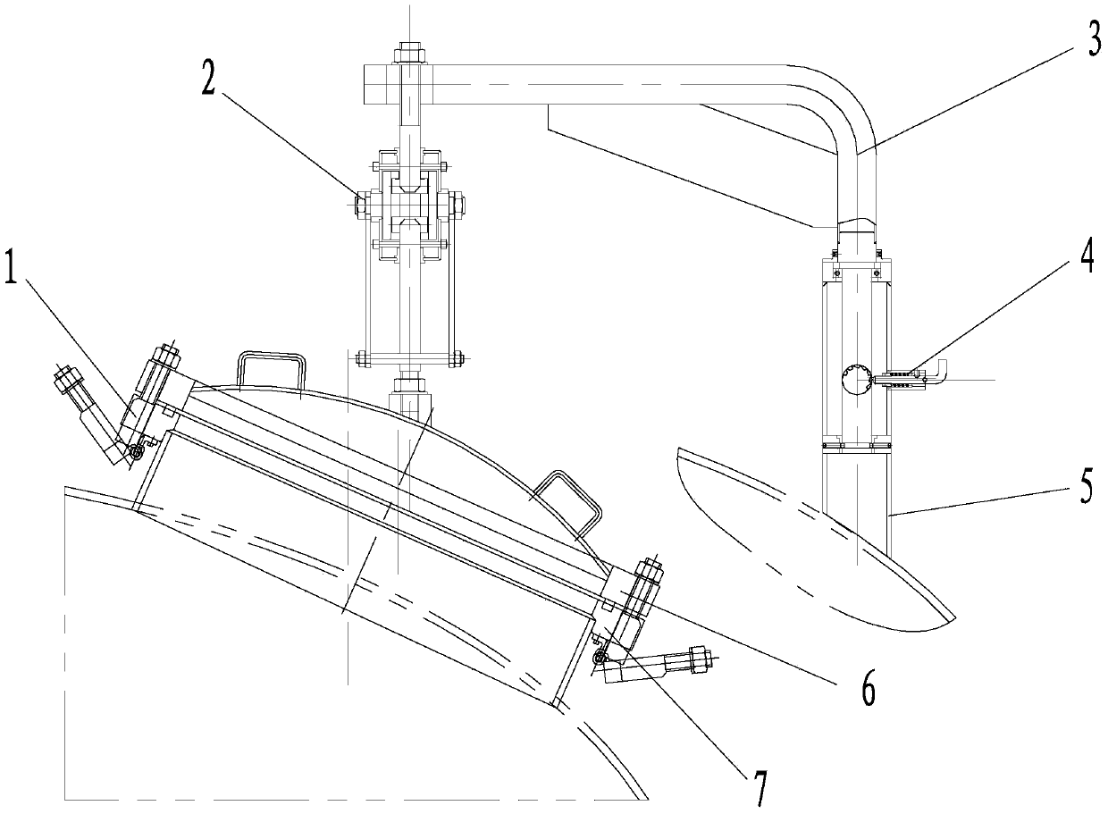
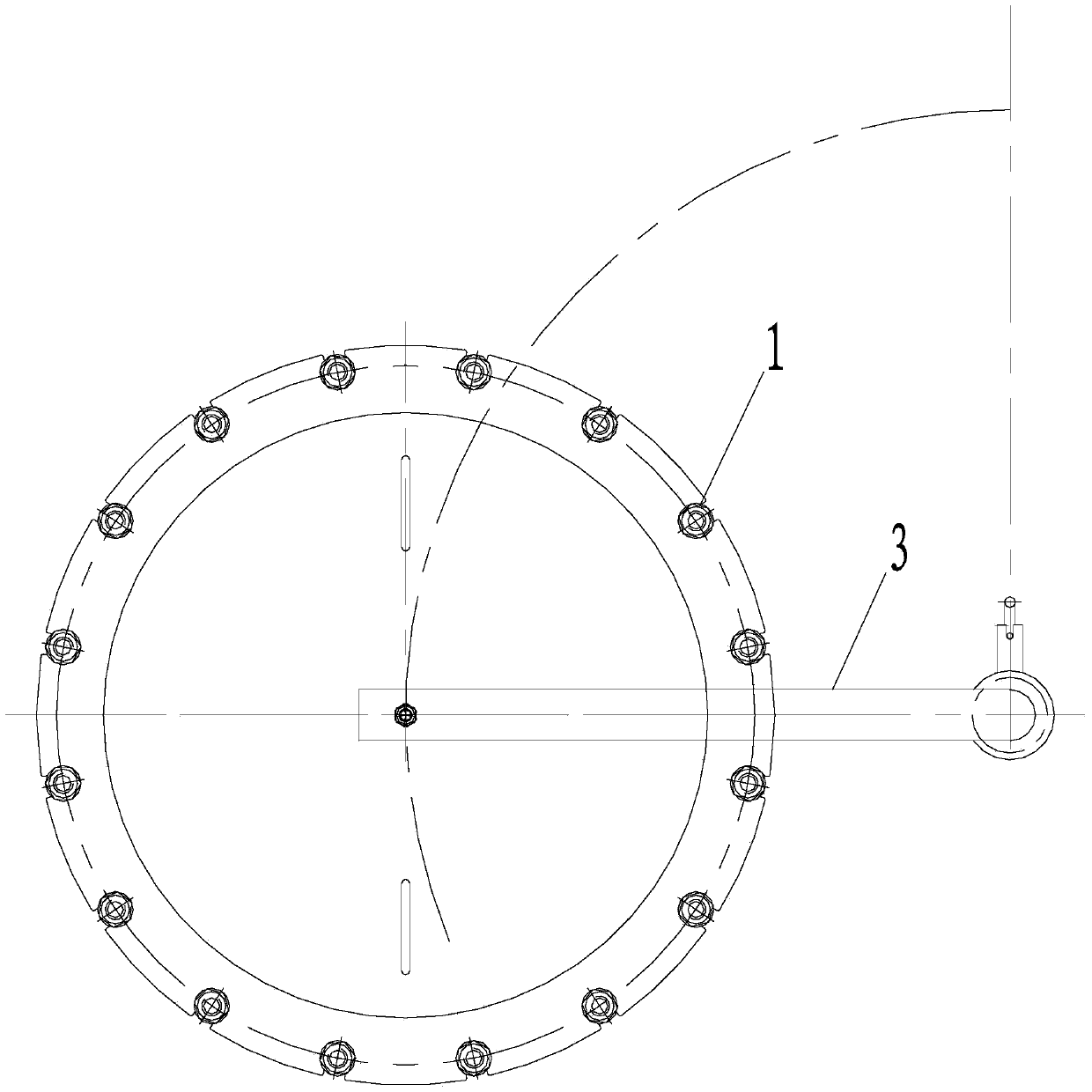
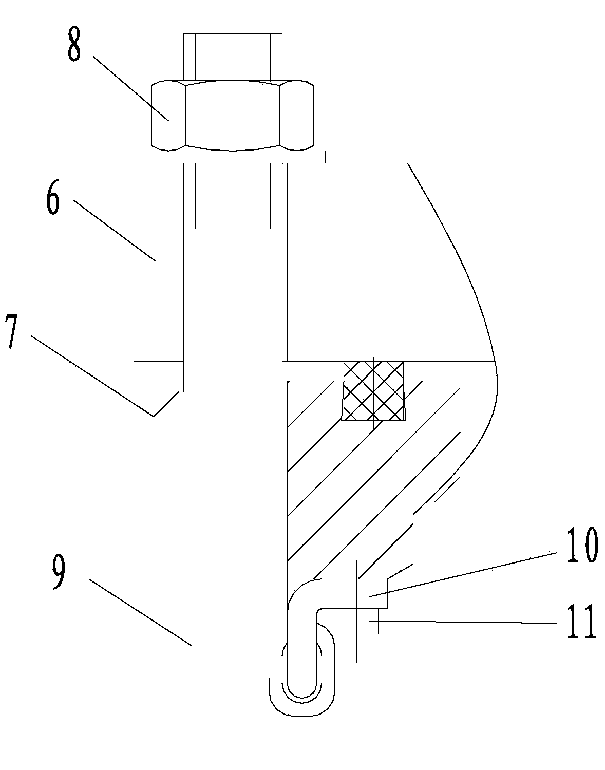
[0025] Such as figure 1 As shown, the present invention discloses a quick-opening manhole, comprising a manhole, a manhole cover, a manhole cover lifting device 2, a slewing boom 3, a slewing boom fixing seat 5, a flip locking bolt 1, and a manhole cover. On the manhole, one end of the manhole cover lifting device 2 is connected with the manhole cover, and the other end is connected with the manhole cover rotary boom 3, the rotary boom 3 is arranged on the rotary boom fixing seat 5, and the manhole is provided Manhole flange 7 is provided with manhole cover flange 6 on the manhole cover. The rotary boom 3 is provided with a rotary boom locking device 4 . Lock the rotary boom locking device 4 while the manhole cover is locked. When the manhole cover needs to be opened, open the rotary boom locking device 4, and lock the rotary crane again when the manhole cover is moved to a suitable position. Arm locking device 4.

[0026] Such as Figure 2-5 As shown, the overturning lock...


PUM


Abstract

The invention provides a quick-opening manhole, wherein a turning-locking bolt is annularly arranged between a manhole and a manhole cover; the turning-locking bolt comprises a bolt part, a boss part and a hanger; the boss part is arranged under the bolt part; the boss part is wider than the bolt part; the hanger is arranged at the lower end of the boss part; a connection part is arranged between the hanger and the manhole flange; a manhole cover lifting device comprises an upper lifting rod, a rotary assembly and a lower lifting rod; the rotary assembly comprises a rotary disk, an oval disk, a rotary shaft and a handle; the rotary shaft is arranged between the oval disk and the rotary disk; the handle is connected with the rotary disk; hollow oval disk is respectively connected with the upper lifting rod and the lower lifting rod in a sliding mode; the upper lifting rod is connected with a rotary suspension arm; and the lower lifting rod is connected with the manhole cover. Through the quick-opening manhole, the strength and rigidity for locking the manhole cover are very reliable; and the quick-opening manhole is simple to operate with safety, convenience and reliability.

Description

technical field [0001] The invention relates to a fermentation device, in particular to a quick-opening manhole. Background technique [0002] There is a manhole device on the top head of each fermenter, which is used as a passage for internal stirring, installation, maintenance, and fermentation process to enter and exit the fermenter. In the existing fermenter manholes, the following generally exist Disadvantages: After using for a period of time, the fixing seat of the falling bolt and the lateral fixed shaft pin or bolt are both subjected to the torque when tightening and loosening, and at the same time, they are distorted and deformed by tension such as bolt pre-tightening and sealing pressure, and cannot be turned over or even cannot be turned over. In normal use, the fixed seat welded on the manhole barrel section is subjected to the same torque and tension, which will deform the barrel section and cause the seal to fail. The strength and rigidity of the manhole cover...

Claims


Application Information

Patent Timeline
IPC IPC(8): C12M1/00
Inventor 方士兴仲伟沧吴瑞和
Owner 江阴德尔热能机械有限公司
Learn More