Anti-clogging aerator
A technology of aerator and air bubbles, which is applied in the field of anti-blocking aerators to achieve the effect of large aeration area, slowing down the rising speed and increasing the distance
- Summary
- Abstract
- Description
- Claims
- Application Information
AI Technical Summary
Problems solved by technology
Method used
Image
Examples
Embodiment 1
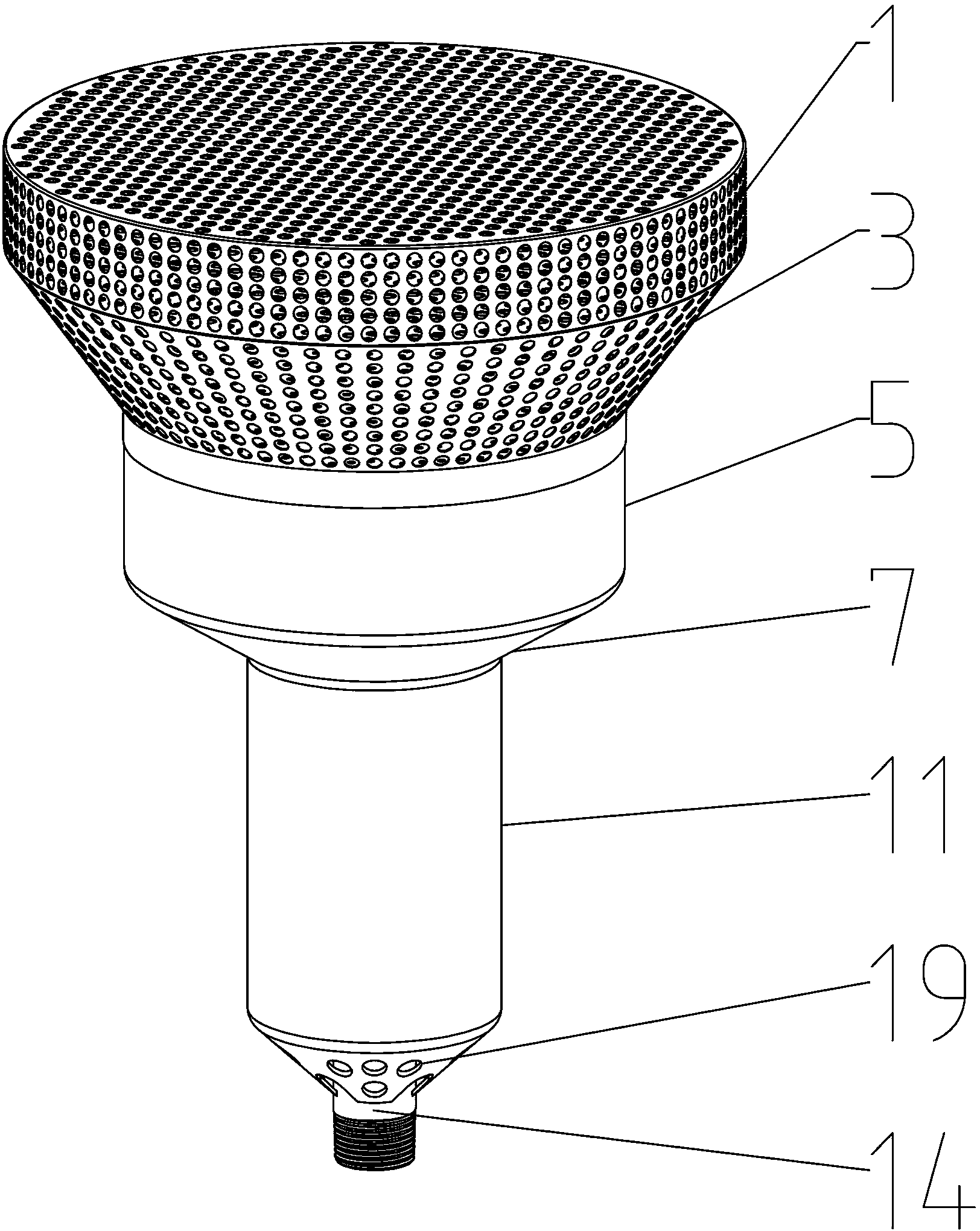
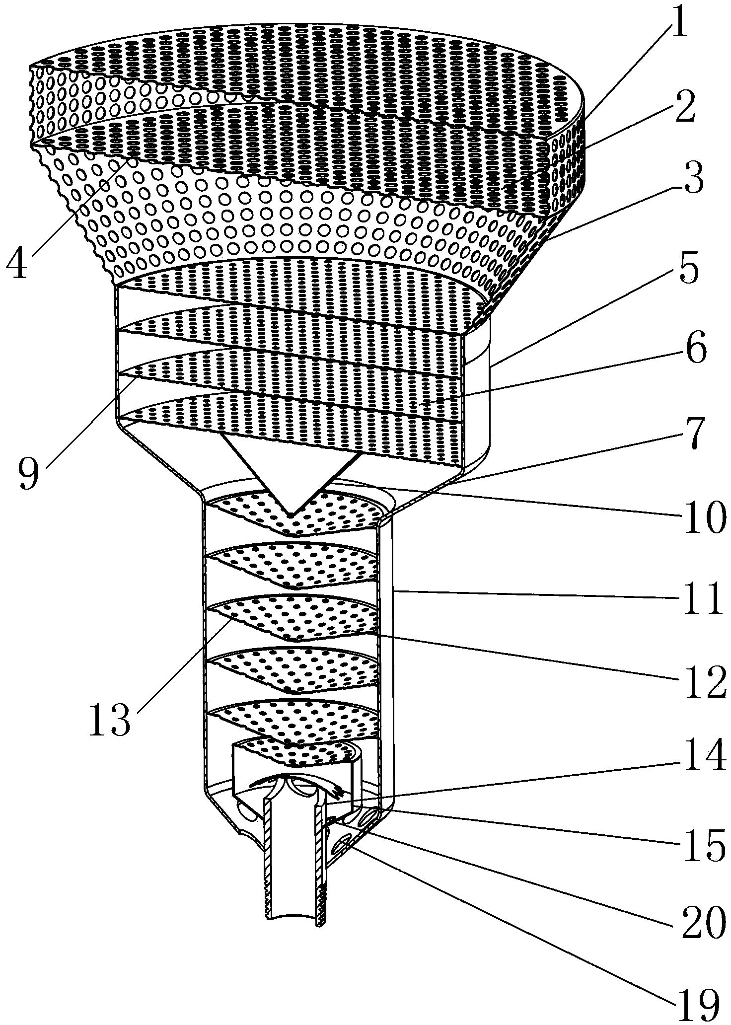
[0033] as attached figure 1 , 2 , 5, and 8, when the anti-blocking aerator of the present invention is a circular tube, the present invention includes an upper air bubble rectifying device, a middle air bubble cutting device, a lower air bubble cutting device and an air intake assembly arranged in the lower air bubble cutting device.
[0034] as attached figure 1 , 2 , 8, the upper air bubble rectifying device of the present invention includes a fairing 1, a rectifying plate 2 horizontally arranged in the fairing 1, and a funnel-shaped fairing transition connection shell arranged between the fairing 1 and the middle air bubble cutting device body 3; the rectifying plate 2 is 1-3 layers, the best shown in the present embodiment is 2 layers, when the rectifying plate 2 is more than 2 layers, the distance between two adjacent layers of rectifying plates 2 is 30-50 mm, The optimal value is 40 mm; the fairing 1, the rectifying plate 2 and the funnel-shaped fairing transition con...
Embodiment 2
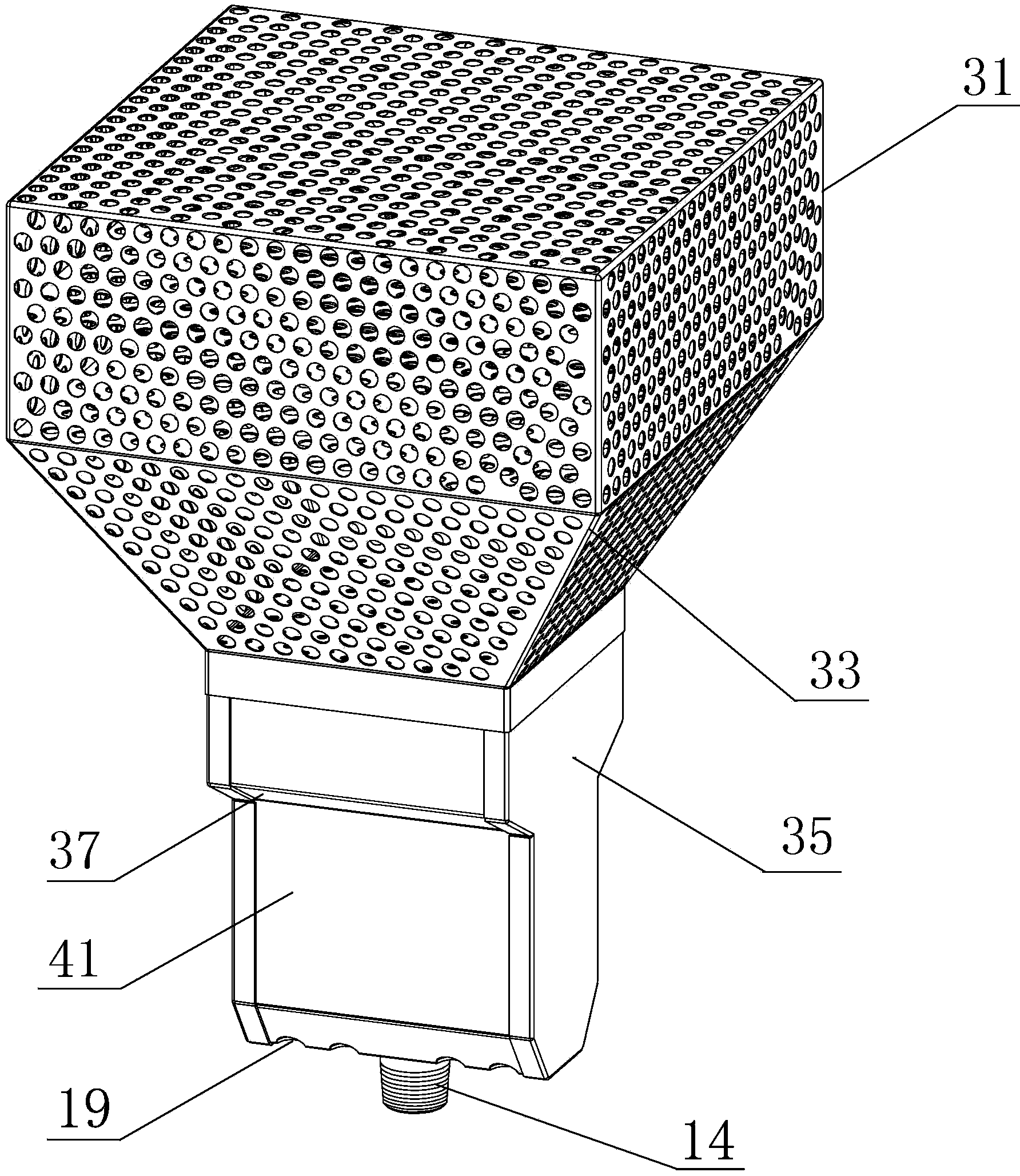
[0041] as attached image 3 , 4 , 6, and 9, when the anti-blocking aerator of the present invention is a square tube, it includes an upper air bubble rectifying device, a middle air bubble cutting device, a lower air bubble cutting device and an air intake assembly arranged in the lower air bubble cutting device.
[0042] as attached image 3 , 4 , 9, the upper air bubble rectifying device of the present invention includes a fairing 31, a rectifying plate 32 horizontally arranged in the fairing 31, and a funnel-shaped fairing transition connection shell arranged between the fairing 31 and the middle air bubble cutting device body 33; the rectifying plate 32 is 1-3 layers, preferably 2 layers, the rectifying plate 32 shown in the present embodiment is 3 layers, when the rectifying plate 32 is more than 2 layers, adjacent two layers of rectifying plates 32 The distance is 30-50 mm, the best is 40 mm; the fairing 31, the rectifying plate 32 and the funnel-shaped fairing transi...
Embodiment 3
[0049] as attached Figure 6 , 7 As shown, the difference between Embodiment 3 of the present invention and Embodiment 2 lies in the structure of the cover body:
[0050] as attached Figure 7As shown, the cover body of the present invention is an air intake horizontal tube 24 whose bottom end communicates with the top of the air intake pipe 14, and the two ends of the air intake horizontal tube 24 are provided with sealing end caps B 25, and the lower part of the air intake horizontal tube 24 is a square Tank body, such a structure can make the mouth of the intake pipe 14 and the intake cross tube 24 be fixed conveniently, and it is easy to combine during processing. The arc surface of the upper semicircular tank of the pipe 24 is provided with air bubble primary cutting holes 18, and the shielding plate is connected with the two sealing end caps B 25 through two support rods.
[0051] When working, when the present invention is installed in the working area, the gas enter...
PUM
| Property | Measurement | Unit |
|---|---|---|
| diameter | aaaaa | aaaaa |
| diameter | aaaaa | aaaaa |
| diameter | aaaaa | aaaaa |
Abstract
Description
Claims
Application Information
 - R&D
- Intellectual Property
- Life Sciences
- Materials
- Tech Scout
- Unparalleled Data Quality
- Higher Quality Content
- 60% Fewer Hallucinations
Browse by: Latest US Patents, China's latest patents, Technical Efficacy Thesaurus, Application Domain, Technology Topic, Popular Technical Reports.
© 2025 PatSnap. All rights reserved.Legal|Privacy policy|Modern Slavery Act Transparency Statement|Sitemap|About US| Contact US: help@patsnap.com


