
The processing technology of the pin gear housing of robot rv reducer

A processing technology, pin gear housing technology, applied in the field of robot RV reducer processing, can solve problems such as high coaxiality, affecting the use accuracy of robot RV reducer, return error, etc., to improve service life and reduce machining allowance and processing costs, reducing the effect of cumulative error

Inactive Publication Date: 2015-11-04
SHANDONG SHKE MACHINERY MFG
View PDF6 Cites 0 Cited by
  • Summary
  • Abstract
  • Description
  • Claims
  • Application Information

AI Technical Summary

Problems solved by technology

[0003] The manufacturing process adopted for the pin gear housing in the prior art is: first process the bearing positions of the two main bearings, and then install the main bearings. The position where the bearing is installed on the pin gear housing is called the bearing position, and the machining accuracy of the bearing positions There are corresponding requirements, and the coaxiality requirements of the two main bearing positions must be high, otherwise there will be a return error during use, which will affect the use accuracy of the robot RV reducer, and the shape tolerance and Position tolerance The assembly error caused by the installation of the main bearing. These accumulated errors are important reasons that affect the use accuracy and service life of the robot RV reducer. Therefore, the importance of the machining accuracy and assembly accuracy requirements of the pin gear housing can be imagined As we know, at present, there is no way to manufacture pintooth housings that meet this requirement in China, and most of them rely on imports.

Method used


Image

  • The processing technology of the pin gear housing of robot rv reducer
  • The processing technology of the pin gear housing of robot rv reducer
  • The processing technology of the pin gear housing of robot rv reducer

Examples


Embodiment Construction

[0027] In order to make the objectives, technical solutions and advantages of the present invention clearer, the following further describes the present invention in detail with reference to the accompanying drawings and embodiments. It should be understood that the specific embodiments described herein are only used to explain the present invention, but not to limit the present invention.

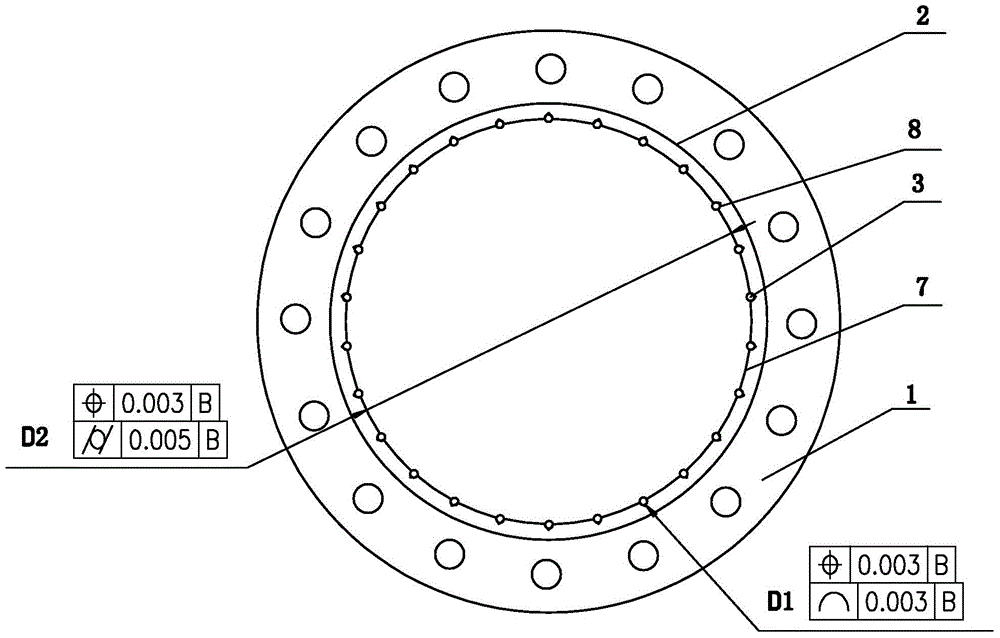
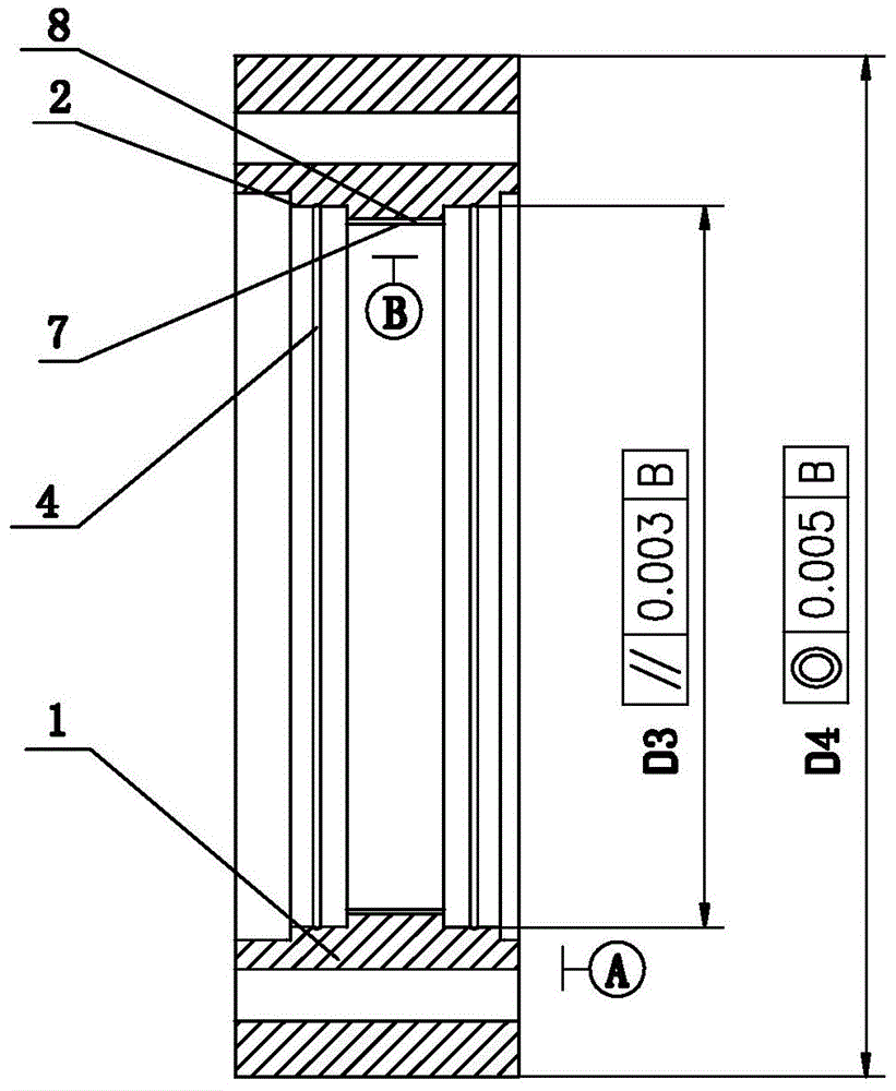
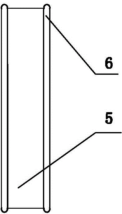
[0028] Such as figure 1 with figure 2 As shown together, the processing technology of the needle gear shell of the robot RV reducer includes the following steps:

[0029] (1) Precision casting or forging the blank of the needle gear shell 1;

[0030] (2) Hot extrusion;

[0031] (3) Machining the outer surface of the blank of the needle gear housing 1 and clamping it, taking the center of rotation of the blank of the needle gear housing 1 as the positioning reference B;

[0032] (4) Machining the end face of the needle gear shell 1 blank, using this end face as the end face reference A, finishing t...


PUM


Abstract

The invention discloses a processing technology of a robot RV speed reducer needle gear shell, and belongs to the technical field of robot RV speed reducer processing. The processing technology includes the steps that precise casting or forging is carried out on a needle gear shell blank; the needle gear shell blank is clamped after the surface of the needle gear shell blank is machined, and the rotation center of the needle gear shell blank is taken as a positioning reference; the end face of the needle gear shell blank, a bearing position of a roller pin bearing and bearing positions of two main bearings are machined; finish machining is carried out on the inner surface of the roller pin bearing according to the positioning reference; finish machining is carried out on a roller pin groove in line contact with a roller pin of the roller pin bearing according to the positioning reference; inner grooves are simultaneously machined in the bearing positions of the two main bearings in a finish machining mode according to the positioning reference; finish machining is carried out on the outer surface of the needle gear blank. The needle gear shell machined according to the steps improves machining precision and the parallelism degree of the bearing positions of the main bearings, guarantees coaxiality, the position degree and cylindricity of the main bearings after installation, achieves one-time clamping, can meet requirements of multiple process parameters, improves machining precision and installation precision of the needle gear shell, reduces accumulated errors, meets the high-precision requirements, and prolongs service life.

Description

Technical field [0001] The invention belongs to the technical field of robotic RV reducer processing, and in particular relates to a processing technology of a needle tooth shell of a robotic RV reducer. Background technique [0002] Robot RV reducer has the advantages of small size, light weight, smooth transmission, no impact, no noise, high motion accuracy, large transmission ratio, and high carrying capacity. It is widely used in electronics, aerospace, robotics and other industries. The structure of the robot RV reducer is complex, including a needle gear shell, a planetary gear carrier, three crankshafts, a cycloidal gear, and three pairs of tapered needle roller bearings installed between the crankshaft and the planetary gear carrier, and eccentrically installed on the crankshaft The three pairs of bearings between the wheel and the cycloidal gear, and the two pairs of bearings installed between the needle gear housing and the planetary carrier. To achieve the accuracy of ...

Claims


Application Information

Patent Timeline
Patent Type & Authority Patents(China)
IPC IPC(8): B23P15/00
Inventor 汤承龙
Owner SHANDONG SHKE MACHINERY MFG
Learn More