Plasma cleaning auxiliary device for components and parts

A technology of plasma cleaning and auxiliary devices, which is applied in the direction of cleaning methods and appliances, chemical instruments and methods, etc., can solve the problems of high cleaning cost, low cleaning efficiency, and easy damage of small-sized components, so as to save cleaning costs and avoid mutual The effect of rubbing, avoiding accumulation and mutual rubbing

Active Publication Date: 2013-12-11
EAST CHINA INST OF OPTOELECTRONICS INTEGRATEDDEVICE
View PDF5 Cites 1 Cited by
  • Summary
  • Abstract
  • Description
  • Claims
  • Application Information

AI Technical Summary

Problems solved by technology

[0005] The purpose of the present invention is to provide an auxiliary device for plasma cleaning of circuit components with high reliability, which overcomes the disadvantages of easy damage to small-sized components, low cleaning efficiency or high cleaning cost during the plasma cleaning process.

Method used


Image

  • Plasma cleaning auxiliary device for components and parts
  • Plasma cleaning auxiliary device for components and parts
  • Plasma cleaning auxiliary device for components and parts

Examples


Embodiment 1

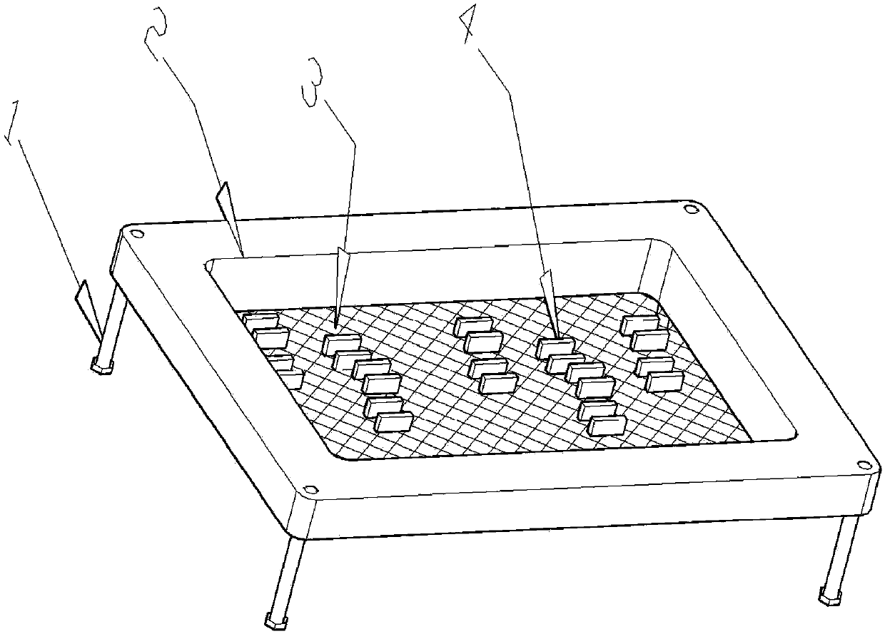
[0021] The overall structure of a plasma cleaning auxiliary device for components provided by the present invention is shown in Figure 1:

[0022] It includes a tray composed of a bracket 1 , a rectangular frame 2 and a tray bottom 3 . Wherein, the bracket 1 is connected with the frame 2 by threads or glued to play a supporting role, and the stainless steel wire mesh 3 of a certain mesh is used as the bottom of the plate and connected with the frame 2 through a stretching process to form a tray with a wire mesh at the bottom.

Embodiment 2

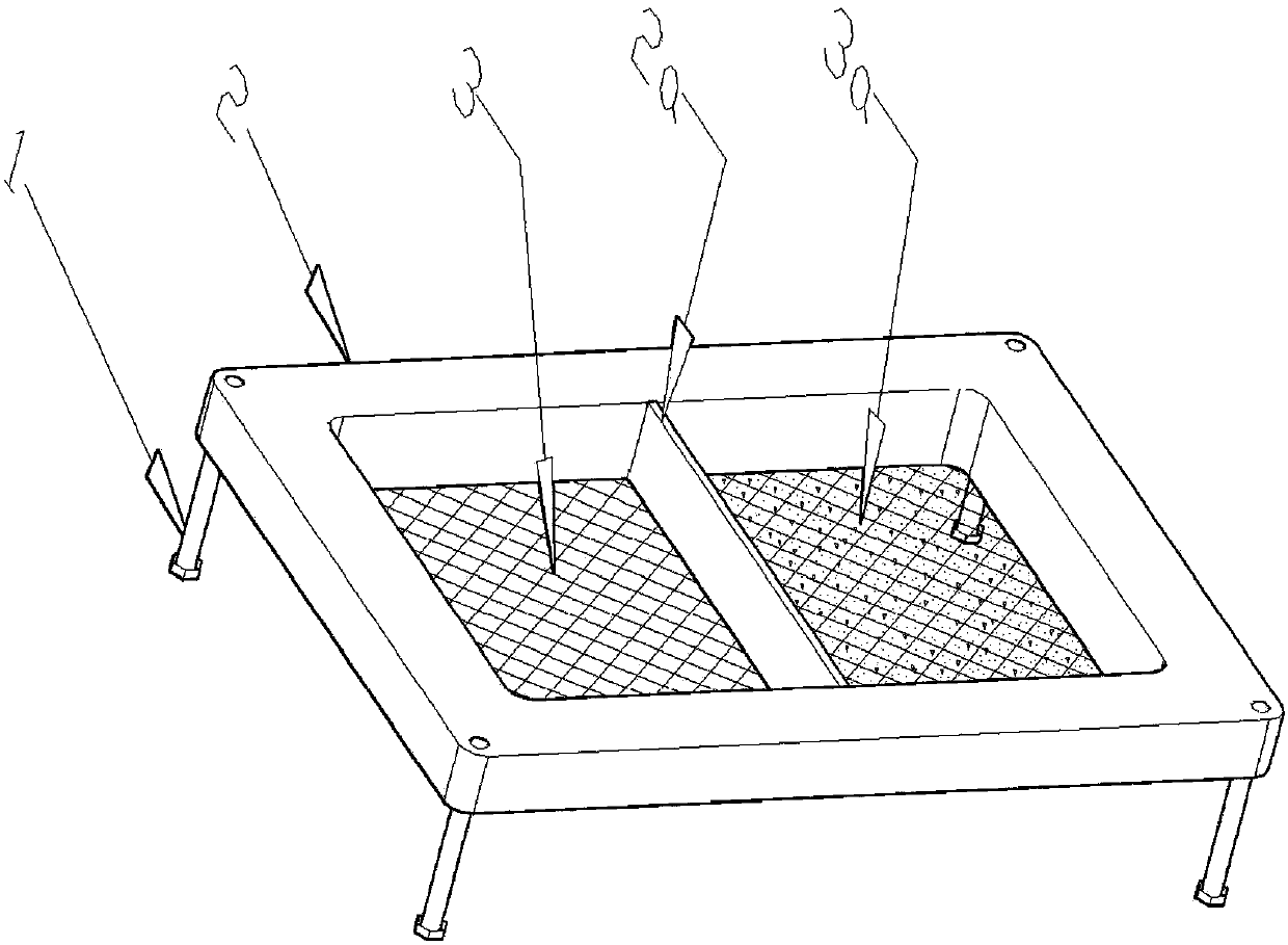
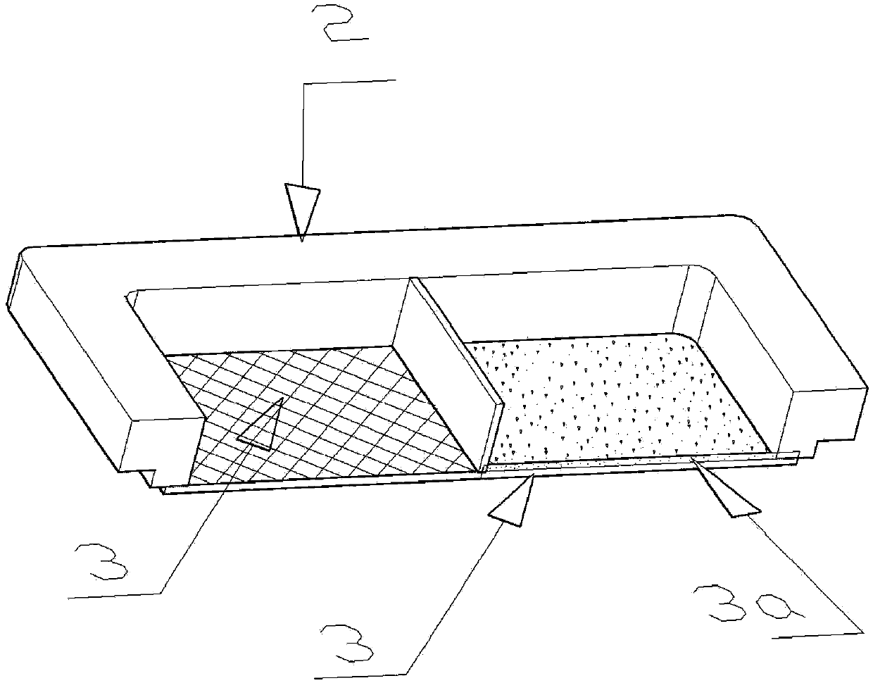
[0024] Such as figure 2 , image 3 As shown, a partition 2a can also be set in the middle of the frame 2 to divide the tray into two areas, one area retains the screen 3 as the bottom of the plate, and the other area uses 704 or 705 silica gel 3a on the bottom screen 3, which is smooth, Spread evenly on screen.

[0025] Figure 4 is the present invention adopts figure 2 The schematic diagram of the cleaning device holding and cleaning components is shown.

[0026] When in use, first place the element 4 to be cleaned on both sides on the screen 3 in the left area, and place it in a single layer to avoid the accumulation and mutual friction of the elements; then put the single-sided cleaning element 5 on the silica gel 3a in the right area, Arranged in a single layer to avoid component accumulation and mutual friction. Then put the cleaning device of the present invention into the plasma cleaning machine, and complete the cleaning process through pumping, air inflation, i...


PUM


Abstract

The invention relates to a plasma cleaning auxiliary device for components and parts. The bottom of a frame (2) is connected with a screen mesh (3) to serve as the bottom of a tray, a partition plate (4) is arranged in the middle of the frame (2) to divide the tray into two areas, and 704 or 705 silica gel (3a) is coated on the screen mesh (3) in one area. When the plasma cleaning auxiliary device is used, an element (4) cleaned in a double-side mode is arranged on the screen mesh (3) on the left area, an element (5) cleaned in a single-side mode is arranged on the silica gel (3a) on the right area, and finally a cleaning device is arranged into a plasma cleaning machine to be cleaned. The plasma cleaning auxiliary device has the advantages that by means of the action of leakage holes of the screen mesh, plasma can bombard the elements from all sides, and the cleaning efficiency is remarkably improved. The screen mesh can dredge and disperse airflow to prevent the elements from being blown by the airflow, piled and rubbed. The silica gel can absorb the components and the parts to prevent the components and the parts from being blown by the airflow, piled and rubbed. Compared with a method using a blue film or a UV film to fix the elements, the plasma cleaning auxiliary device removes a special film shifting machine and a special ultraviolet light machine and saves cleaning cost.

Description

technical field [0001] The invention relates to the field of electronic product manufacturing, in particular to a plasma cleaning device before assembly of components of microelectronic products. Background technique [0002] The plasma cleaning process mainly uses active plasma with a certain energy to perform dual effects of physical bombardment and chemical reaction on the object to be cleaned, so that the surface material of the object to be cleaned becomes particles and gaseous substances, which are then vacuumed out to achieve the purpose of cleaning. The pumping, filling, and ion bombardment and chemical reactions in the plasma cleaning process are the main processes. [0003] Assembled circuits with high reliability quality level, in order to improve the reliability of assembly, it is necessary to use plasma cleaning method to remove the oxidation of the welding surface of the components (mainly passive terminal electrode components and active device bare chips) befo...

Claims


Application Information

Patent Timeline
Patent Type & Authority Applications(China)
IPC IPC(8): B08B13/00
Inventor 李波夏俊生李寿胜侯育增李文才
Owner EAST CHINA INST OF OPTOELECTRONICS INTEGRATEDDEVICE
Why Eureka
Try Eureka