
Fed material crusher, crushing tooth roller and crushing tooth assembly thereof

A crushing tooth and assembly technology, applied in grain processing, etc., can solve problems such as large assembly volume, complex assembly structure, and scraper jamming

Active Publication Date: 2013-12-11
HUNAN WANTONG TECH
View PDF9 Cites 17 Cited by
  • Summary
  • Abstract
  • Description
  • Claims
  • Application Information

AI Technical Summary

Problems solved by technology

[0003] At present, during the working process of the existing crushing tooth assembly, the materials to be processed or crushed will be conveyed through the scraper conveyor located under the crushing tooth assembly. However, due to the relatively It is complex, and its assembly volume is large. During the operation of the equipment, it is easy to squeeze the material below the crushing tooth assembly. The force formed during the extrusion process will be transferred to the scraper conveyor below by the material, resulting in The friction between the related components of the scraper conveyor increases, which in turn accelerates the wear of its related parts, and even causes accidents such as scraper jamming, which seriously affects the overall operation stability and continuity of the feeder crusher.

Method used


Image

  • Fed material crusher, crushing tooth roller and crushing tooth assembly thereof
  • Fed material crusher, crushing tooth roller and crushing tooth assembly thereof
  • Fed material crusher, crushing tooth roller and crushing tooth assembly thereof

Examples


Embodiment Construction

[0024] The core of the present invention is to provide a crushing tooth assembly, which has a simple assembly structure and is not easy to generate extrusion force perpendicular to the material conveying direction on the material; it also provides a crushing tooth assembly using the above crushing tooth assembly A broken toothed roller; at the same time, a feed crusher using the above crushed toothed roller is provided.

[0025] In order to enable those skilled in the art to better understand the solution of the present invention, the present invention will be further described in detail below in conjunction with the accompanying drawings and specific embodiments.

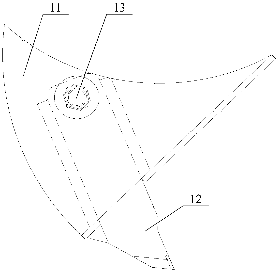
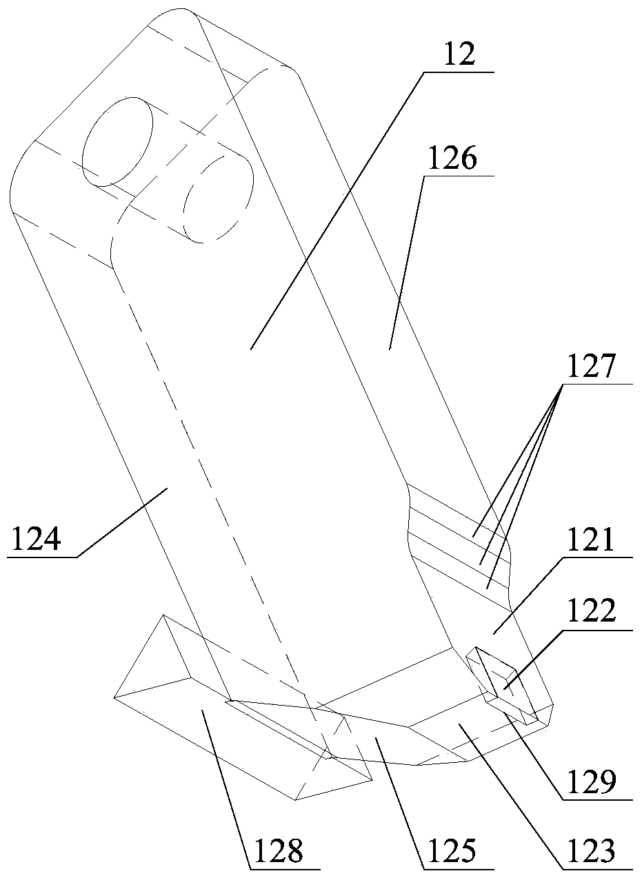
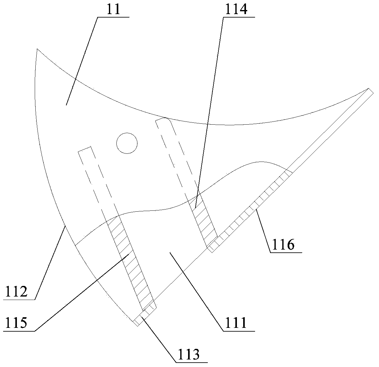
[0026] Please refer to figure 1 , figure 2 with image 3 , figure 1 It is a schematic diagram of the assembly structure of the crushing tooth assembly provided by a specific embodiment of the present invention; figure 2 for figure 1 Schematic diagram of the assembly structure of the middle crushing knife too...


PUM


Abstract

The invention discloses a crushing tooth assembly. A crushing cutter tooth is inserted in a cutter tooth installing hole in the middle of the front end face of a tooth holder, the lower bottom surface of the tooth holder is an arc surface, the lower bottom surface of the tooth holder is tangent to a material conveying direction, a front cutter surface is arranged at the front end part of the upper surface of the crushing cutter tooth, a cutter is arranged at the front end of the front cutter surface, a main rear cutter surface is arranged on the front end face of the crushing cutter tooth, and an included angle between the main rear cutter surface and the front cutter surface is an acute angle. In a working process, because the lower bottom surface of the tooth holder is the arc surface tangent to the material conveying direction and the included angle between the main rear cutter surface and the front cutter surface is the acute angle, an extruding force of relevant parts of the crushing tooth assembly to materials in a running process of the crushing tooth assembly can be effectively reduced or avoided, and further the abrasion of a scraper conveyer below the crushing tooth assembly and among the relevant parts is prevented; and an integral assembling structure of the crushing tooth assembly is simple and reliable. The invention also discloses a crushing tooth roller adopting the crushing tooth assembly and a fed material crusher adopting the crushing tooth roller.

Description

technical field [0001] The invention relates to the technical field of feed crushers, in particular to a crushing tooth assembly and a crushing tooth roller using the crushing tooth assembly. The invention also relates to a feed crusher using the crushing gear roller. Background technique [0002] Feed crusher is a kind of construction machinery equipment used for material conveying and transfer, and the crushing tooth assembly is the main material processing device of feed crusher, and its working performance is also widely concerned by people. [0003] At present, during the working process of the existing crushing tooth assembly, the materials to be processed or crushed will be conveyed through the scraper conveyor located under the crushing tooth assembly. However, due to the relatively It is complex, and its assembly volume is large. During the operation of the equipment, it is very easy to squeeze the material below the crushing tooth assembly. The force formed during...

Claims


Application Information

Patent Timeline
IPC IPC(8): B02C4/30
Inventor 彭红娜方义飞张春伟
Owner HUNAN WANTONG TECH
Learn More