
Reaction solution viscosity detection method, reaction solution viscosity detection device, method for obtaining reaction product, and manufacturing device for obtaining reaction product

A technology of reaction products and reaction liquids, applied in the field of manufacturing equipment for obtaining reaction products, can solve problems such as difficulty in popularization, long delivery time, and increased installation costs of viscometers

Inactive Publication Date: 2013-12-04
DIC CORP
View PDF5 Cites 5 Cited by
  • Summary
  • Abstract
  • Description
  • Claims
  • Application Information

AI Technical Summary

Problems solved by technology

There is a problem that a rotation speed measuring instrument that satisfies the explosion-proof standard is expensive, not only increases the installation cost of the viscometer, but also has a long lead time, and the installation is accompanied by a production stop, so it is difficult to achieve popularization

Method used


Image

  • Reaction solution viscosity detection method, reaction solution viscosity detection device, method for obtaining reaction product, and manufacturing device for obtaining reaction product
  • Reaction solution viscosity detection method, reaction solution viscosity detection device, method for obtaining reaction product, and manufacturing device for obtaining reaction product
  • Reaction solution viscosity detection method, reaction solution viscosity detection device, method for obtaining reaction product, and manufacturing device for obtaining reaction product

Examples


Embodiment

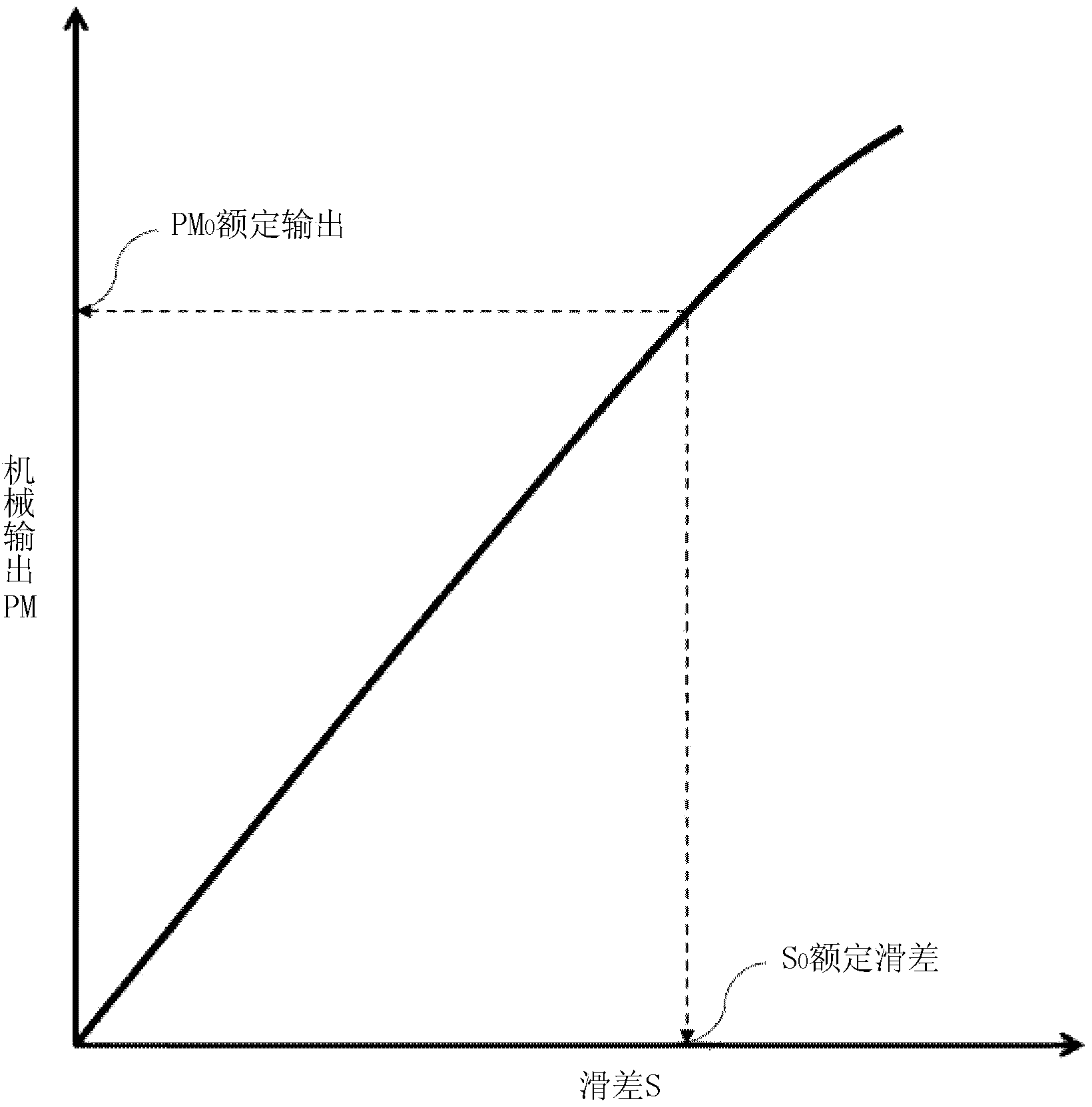
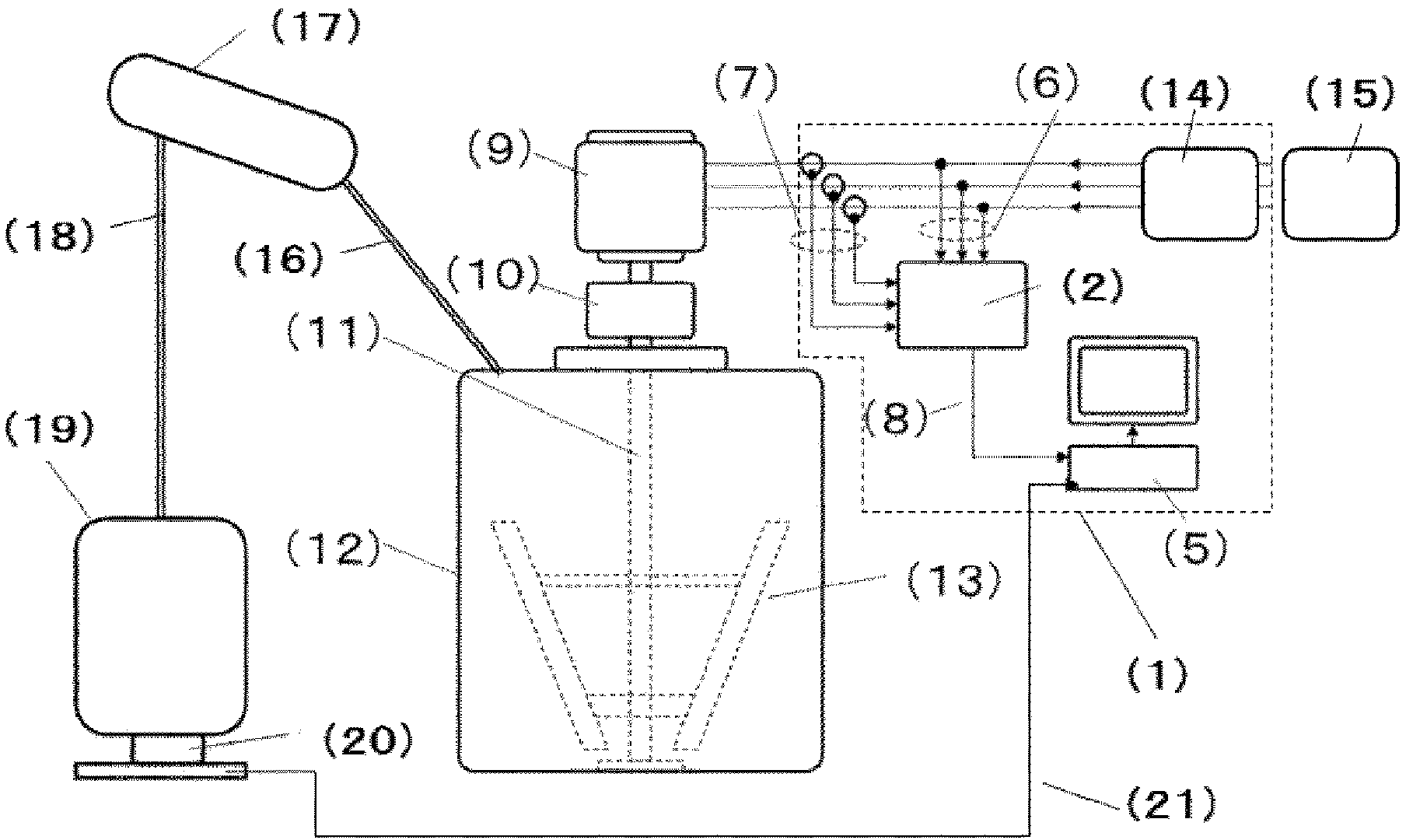
[0215] An example in which the present invention is applied to the production of a reaction solution containing a phenolic resin will be described below. Among them, used in the manufacture of this reaction solution image 3 device shown. The specifications of the induction motor 9 are as follows.

[0216] Specifications of three-phase induction motor (Y connection line)

[0217] Capacity: 15kW Rated speed: 1460 revolutions per minute (rated slip 0.0266)

[0218] Rated voltage: 200V Rated current: 57A Rated frequency: 50Hz

[0219] Number of poles: 4

[0220] Primary coil resistance: 0.0943Ω

[0221] Primary coil reactance: 0.725Ω (at rated frequency)

[0222] Secondary coil resistance: 0.0130Ω

[0223] Secondary coil reactance: 0.0320Ω (at rated frequency)

[0224] Resistance measurement standard temperature: 20°C Resistance temperature coefficient: 234.5

[0225] Mechanical loss: 70W (at rated speed)

[0226] Iron loss: 335W (design value: hysteresis loss 115W, edd...


PUM

PropertyMeasurementUnit
Resistanceaaaaaaaaaa
Iron lossaaaaaaaaaa

Abstract

The present invention relates to a reaction product viscosity detection method having a viscosity detection process including a rotation speed detection process and other processes. The rotation speed detection process is a process for detecting the rotation speed of an induction motor in which the power loss (PL) occurring when power (P) is supplied consists of a power loss (A) and a power loss (B) and includes: a step (?) in which the difference between the power (P) and the power loss (A) is assumed to be a first-order approximation value (PM1) of the mechanical output of the induction motor and a first-order approximation value of the rotation speed given by the equation N1 = NS(1 - S1) is obtained from the relationship between the output (PM1) of the induction motor and slip (S1) given by the equation PM1 = ?S1; a step (??) in which the power loss (B1) is obtained based on the first-order approximation value (N1); and a step (???) in which a second-order approximation value (PM2) is assumed to be given by the equation P - (A + B1) and a second-order approximation value given by the equation N2 = NS(1 - S2) is obtained from the relationship between the output (PM2) and slip (S2) given by the equation PM2 = ?S2.

Description

technical field [0001] The present invention relates to a method for detecting the viscosity of a reaction liquid using an induction motor as a power source, a viscosity detection device for the reaction liquid, a method for obtaining a reaction product, and a manufacturing device for obtaining the reaction product. Background technique [0002] The inventors of the present invention have proposed a reaction liquid viscosity detection device installed in a reactor in which the reaction liquid is stirred by rotating the stirring blades with an induction motor driven by an inverter (inverter) as a power source ( Patent Document 1). This detection device is characterized in that it has each unit of the following 1) to 5), and the input power (P I ), power loss (P L ), angular velocity (ω) as the basis, through T=(P I -P L ) / ω to obtain the rotational torque (T), and calculate the viscosity of the reaction liquid from the rotational torque. [0003] 1) A power measuring ins...

Claims


Application Information

Patent Timeline
IPC IPC(8): G01N11/14G01L5/00G01P3/44
CPCG01P3/26G01P3/44G01N11/142G01N2011/0053G01N11/14
Inventor 蛯泽胜英今泉规史鹿毛孝和大岛和久山田昭宏
Owner DIC CORP
Learn More