
Multi-rotation hydraulic valve

A rotary valve technology, applied in rotary piston engines, rotary or oscillating piston engines, valve details, etc., can solve the problems of small valve driving force, valve impact, low air source pressure, etc. Lock, reduce shock and vibration, improve reliability

Active Publication Date: 2013-12-04
沈阳锐维液压设备制造有限公司
View PDF9 Cites 4 Cited by
  • Summary
  • Abstract
  • Description
  • Claims
  • Application Information

AI Technical Summary

Problems solved by technology

In the application practice, it is found that the above-mentioned driving method still has some shortcomings and deficiencies
The electric valve has a small instantaneous starting torque, which makes the valve unreliable to open. Due to the large moment of inertia when the reducer is running, the impact on the valve is also large. Because the electric valve is driven by a motor, it is not suitable for flammable and explosive applications such as oil and natural gas. occasion application
Due to the large volume of the equipment and the low pressure of the gas source, the pneumatic valve has a small driving force on the valve, and the compressibility of the gas will cause the valve to run unstable.
The hydraulic valves that have been used at present refer to valves driven by oil cylinders. Due to the floating nature of oil cylinder pistons, it is difficult for the valve plate in the valve to lock itself, and it is not easy to realize emergency manual operation.
On the other hand, due to the cylinder stroke, the hydraulic valve will cause the external dimension of the hydraulic valve to be super high or super wide.

Method used


Image

  • Multi-rotation hydraulic valve
  • Multi-rotation hydraulic valve
  • Multi-rotation hydraulic valve

Examples


Embodiment 1

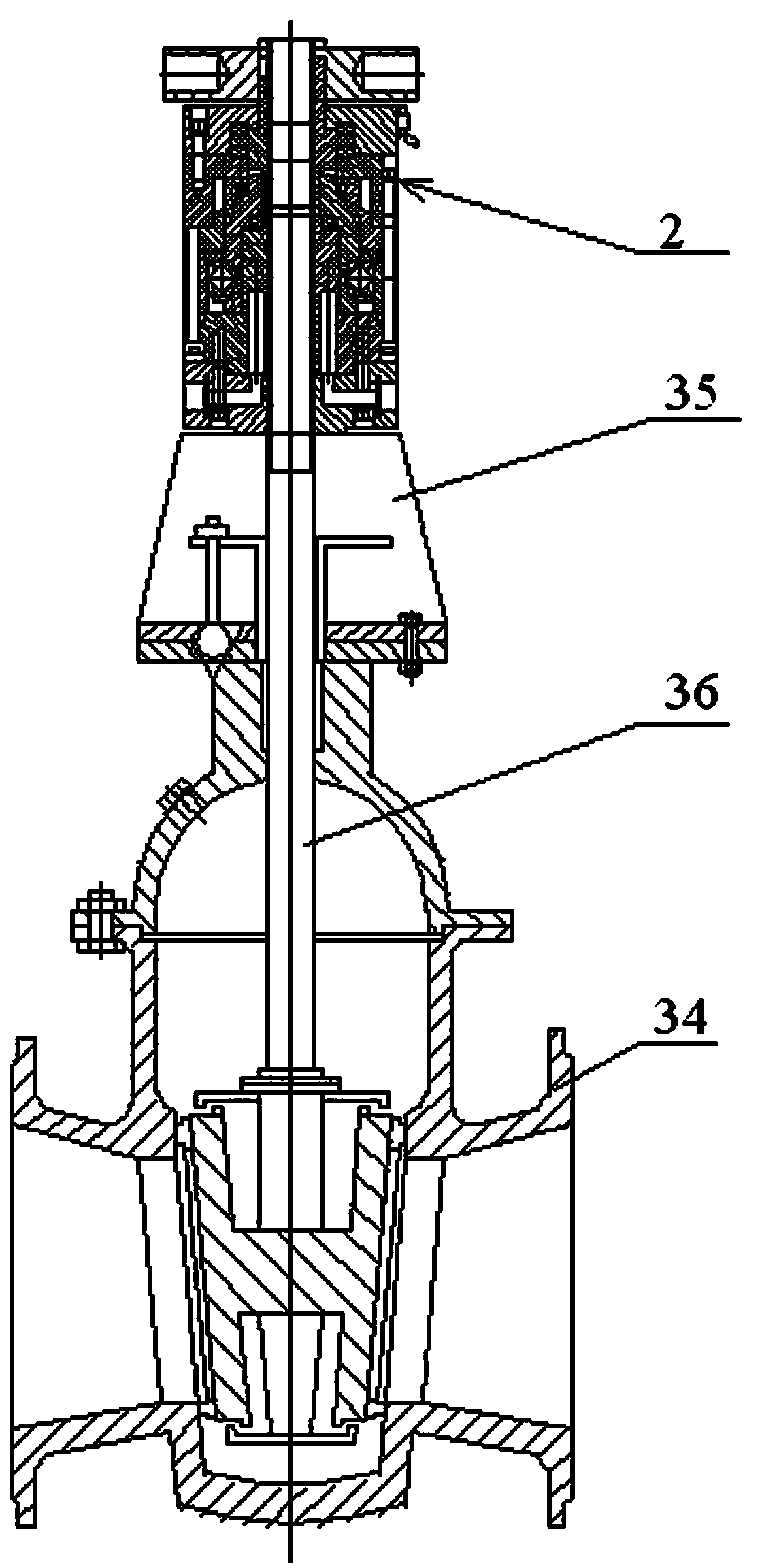
[0025] A multi-turn hydraulic valve includes a hydraulic motor 2, a valve 34 and a connecting bracket 35.

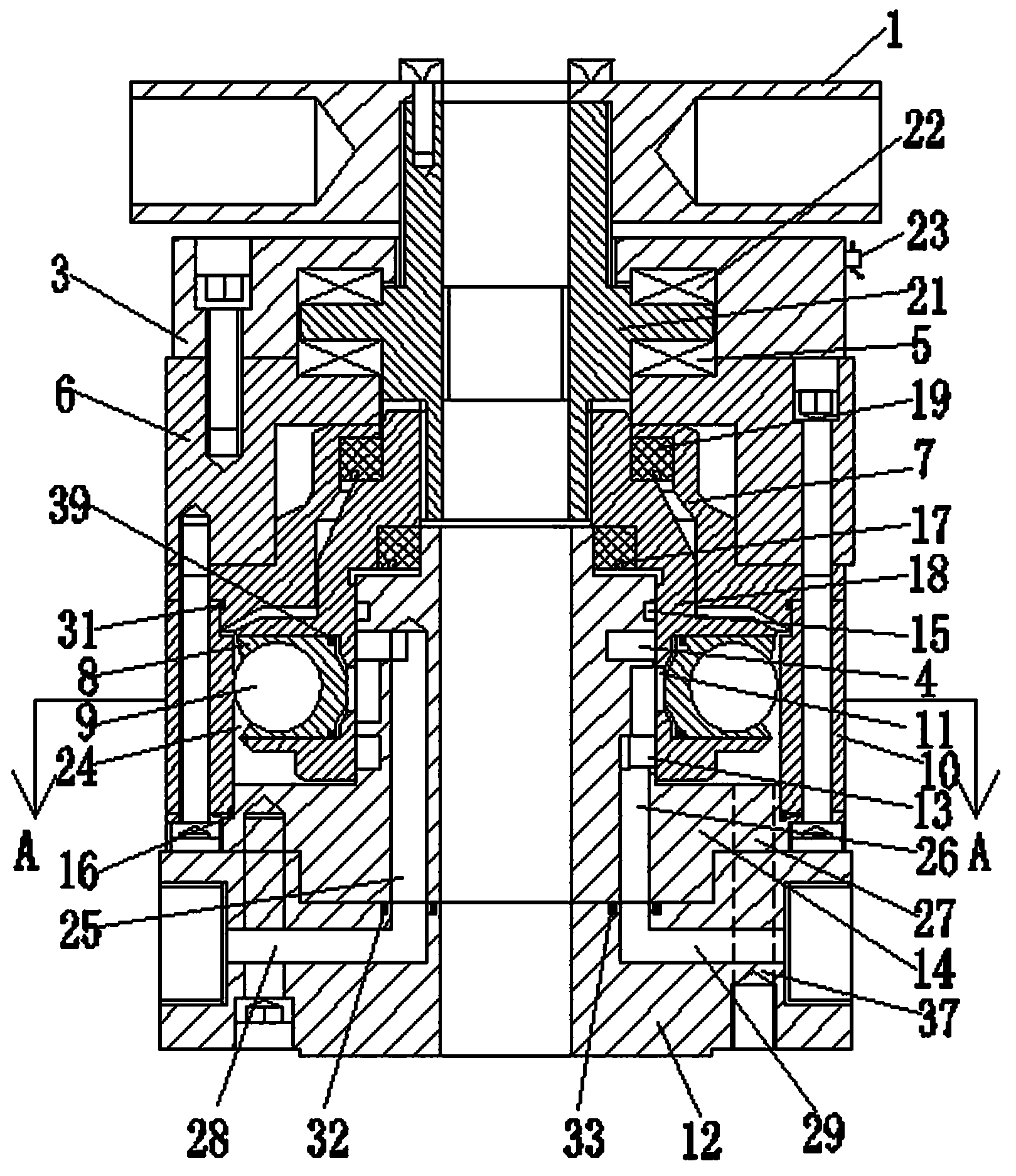
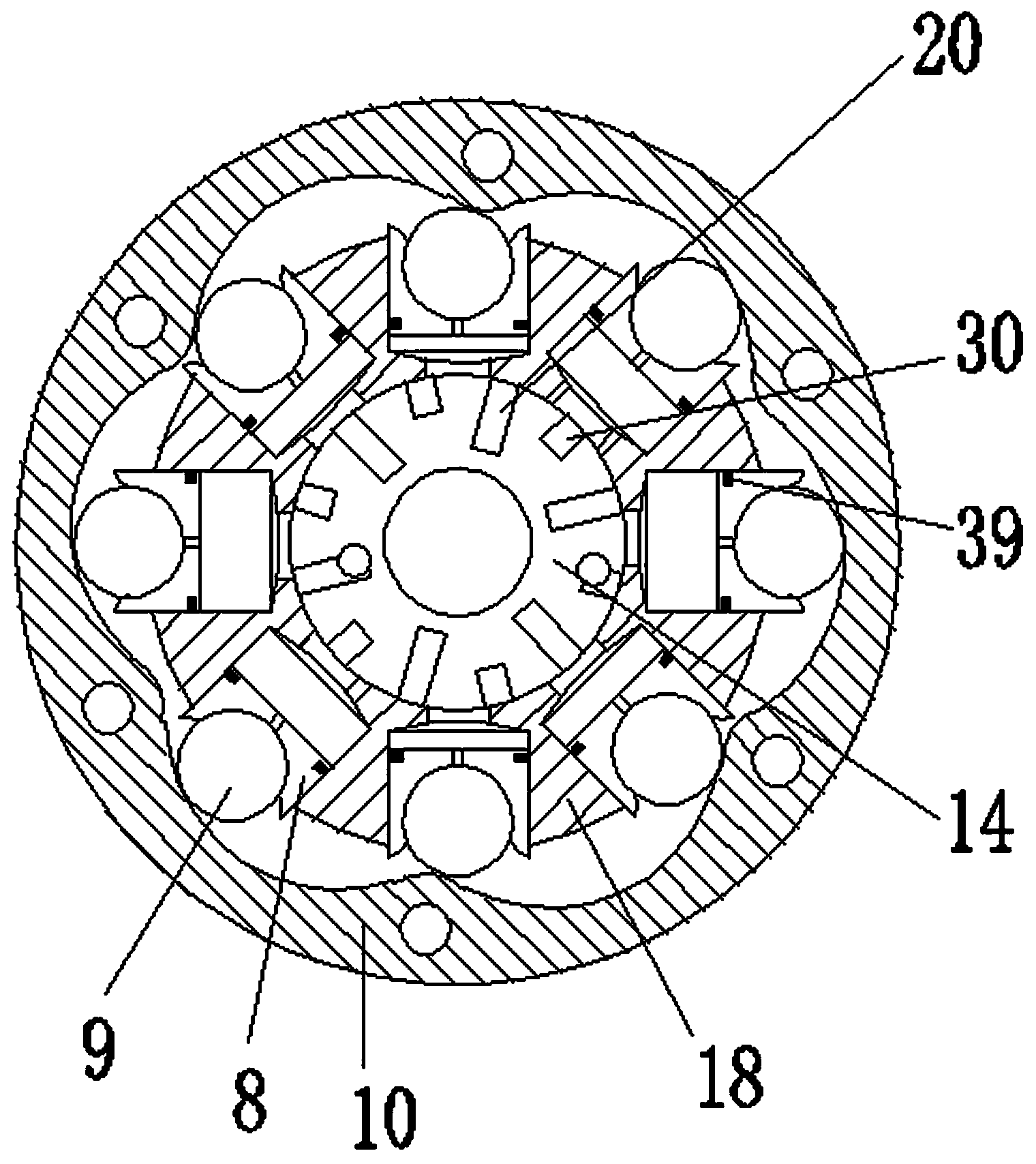
[0026] The hydraulic motor includes a manual hinge plate 1, a bearing end cover 3, a bearing seat 6, an output sleeve 21, a rotor 18, a sealing end cover 7, a stator 10, an oil distribution sleeve 14 and a lower end cover 12;

[0027] The bearing end cover 3 is fixedly connected with the bearing seat 6 through a plurality of screws, and both the bearing seat 6 and the bearing end cover 3 have a center hole; there is a step in the center hole of the bearing end cover 3, and the first thrust bearing 22 is installed, and the bearing seat 6 The second thrust bearing 5 is installed in the annular groove on the upper end surface; the output sleeve 21 is installed in the inner cavity surrounded by the bearing end cover 3 and the bearing seat 6, and is connected with the first thrust bearing 22 and the second thrust bearing The inner rings of 5 are separately fitted and fixed on...

Embodiment 2

[0036] The second embodiment is basically the same as the first embodiment, except that the valve 34 is a dark rod valve structure (see Figure 4 ), the elevating rod 38 does not move up and down. The lifting rod 36 in the first embodiment is composed of a solid upper valve stem connected with a lower valve stem. The upper end of the upper valve stem is connected with the key or tooth in the inner hole of the output sleeve 21 in the hollow plunger motor. The nuts fixed on the valve plate of the dark rod valve are connected by threads.

[0037] The rotation of the motor drives the upper and lower valve stems to rotate, and the nut drives the valve plate up and down along the rotation direction of the valve stem.


PUM


Abstract

The invention discloses a multi-rotation hydraulic valve which comprises a hydraulic motor, a valve and a connection support. The hydraulic motor comprises a manual capstan, a bearing end cover, a bearing pedestal, an output sleeve, a rotor, a sealing end cover, a stator, an oil distribution sleeve and a lower end cover, wherein a lifting rod of the valve can pass through the motor, and the motor rotates to drive the output sleeve and drives the lifting rod to open and close the valve. The hydraulic motor is used for safely and reliably driving and controlling the multi-rotation valve, a hydraulic system can automatically detect the load change of the valve in the process of operation, the output torque and the rotation speed of the hydraulic motor are automatically regulated, the opening and closing flexible control, automation and intelligentization of the valve are achieved, and impact and vibration on the valve are reduced. Remotely arranging the hydraulic system to control the valve remotely can avoid the risks, the application field can be expanded to highly-polluted, combustible and explosive petroleum and natural gas storing and conveying occasions and other occasions. The multi-rotation hydraulic valve further has a mechanical self-locking function and an emergency manual operation function.

Description

technical field [0001] The invention relates to a general mechanical valve, in particular to a multi-rotary hydraulic valve. Background technique [0002] As a key component in pipeline transportation of liquid and gas media, valves are widely used in many fields such as petroleum, natural gas, oil and gas terminals, chemical industry, ships, power stations, metallurgy, and municipal administration. In recent years, with the enlargement of engineering projects, the demand for large-diameter and large-size valves has been increasing, and manual operation has become very difficult and cannot keep up with the requirements of the times. In order to meet the needs of the automation system, a variety of valve drive methods have appeared, such as electric valves driven by motor accelerators, pneumatic valves driven by cylinders, hydraulic valves driven by oil cylinders, etc. In the application practice, it is found that the above-mentioned driving method still has some shortcoming...

Claims


Application Information

Patent Timeline
IPC IPC(8): F16K31/12F03C2/00
Inventor 徐学新
Owner 沈阳锐维液压设备制造有限公司
Learn More