Eureka AIR delivers breakthrough ideas for toughest innovation challenges, trusted by R&D personnel around the world.

Topological structure of power converter of electric car switch reluctance motor

A technology of switched reluctance motors and power converters, which is applied in motor generator control, electric vehicles, and conversion of AC power input to DC power output. , reduce pollution, good effect

Inactive Publication Date: 2013-11-27
CHINA UNIV OF MINING & TECH
View PDF7 Cites 45 Cited by
  • Summary
  • Abstract
  • Description
  • Claims
  • Application Information

AI Technical Summary

Problems solved by technology

However, the problem existing in the existing switched reluctance motor drive system technology is that it cannot realize the three working states of "electric, braking and charging" at the same time.
The DC / DC Boost converter can increase the power supply voltage of the switched reluctance motor power converter, but it is a one-way converter. When the motor is demagnetized and braked, the pulse current directly charges the battery. When the feedback current is too large, it can Damage to the battery

Method used


Image

  • Topological structure of power converter of electric car switch reluctance motor
  • Topological structure of power converter of electric car switch reluctance motor
  • Topological structure of power converter of electric car switch reluctance motor

Examples


Embodiment 1

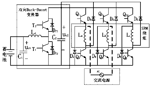
[0015] Embodiment 1: Add a bidirectional Buck-Boost converter before the asymmetrical half-bridge power converter of the switched reluctance motor; the described bidirectional Buck-Boost converter includes a capacitor C 1 , capacitance C 2 , switch tube T 1 , switch tube T 2 , Freewheeling diode D T1 , Freewheeling diode D T2 and inductance L d ; switch tube T 1 The collector and switch tube T 2 The emitter is connected to the switching tube T 2 The collector is the positive output terminal, the switching tube T 1 The emitter of the pole is the negative output terminal, the capacitor C2 is connected to the positive input terminal and the negative output terminal, and the switch tube T 1 and switching tube T 2 There are freewheeling diodes D connected in parallel on the collector and emitter respectively. T2 , Freewheeling diode D T1 ; Capacitance C 1 and inductance L d Constitutes an LC type filter, the inductance L d One end is connected to the switch tube T 1 ...


PUM


Abstract

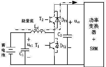
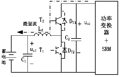
The invention discloses a topological structure of a power converter of an electric car switch reluctance motor. A two-way Buck-Boost converter is added to the front portion of a dissymmetric half-bridge power converter of the switch reluctance motor. When the switch reluctance motor operates in the power-driven state, boosting of a storage battery is achieved through a forward Boost-DC / DC converter body, so that electricity is provided for the dissymmetric half-bridge power converter of the switch reluctance motor; when the switch reluctance motor operates in the braked state, the storage battery is charged by the dissymmetric half-bridge power converter of the switch reluctance motor through a backward Buck converter, so that kinetic energy of an electric car is converted into electric energy of the storage battery; when the electric car operates in the charging state, the switch reluctance motor does not rotate, a vehicle-mounted charger is formed by an alternating current power source through a winding of the switch reluctance motor and the dissymmetric half-bridge converter, the storage battery is directly charged by the vehicle-mounted charger, an externally-connected element is not needed, an alternating current is converted into a direct current, the storage battery is charged by the direct current through a Buck converter body, so that power factor correction is achieved, the reliability and the flexibility of a system are effectively improved, the practicality is high, and the universality is strong.

Description

technical field [0001] The invention relates to a switched reluctance motor drive system, in particular to a topological structure of a power converter of a switched reluctance motor for an electric vehicle. Background technique [0002] The switched reluctance motor has a simple and firm structure; high reliability and robustness; large starting torque; wide speed range; high efficiency in a wide speed and torque working area; regenerative braking , to recover energy, so it is suitable for electric vehicle drive system. However, the problem existing in the existing switched reluctance motor drive system technology is that it cannot realize the three working states of "electric, braking and charging" at the same time. For the battery-powered electric vehicle switched reluctance motor drive system, the use of DC / DC front-end converters can increase the power supply voltage of the power converter, reduce the supply current, reduce the volume of the power converter, and improv...

Claims


Application Information

Patent Timeline
Patent Type & Authority Applications(China)
IPC IPC(8): H02M3/07H02P27/06H02J7/02H02J7/14
CPCY02T10/7022Y02T10/7033H02M3/00H02P2201/07H02M1/4233H02M7/5387H02P25/092B60L7/14B60L15/007B60L2210/12B60L2210/14B60L2210/40B60L2220/18Y02T10/64Y02T10/72
Inventor 陈昊程鹤
Owner CHINA UNIV OF MINING & TECH
Why Eureka
Eureka Blog
Learn More