Reducer sleeve

A technology of sliding sleeve and diameter reduction, which is applied in the direction of production fluid, wellbore/well components, earthwork drilling and production, etc., which can solve the problem of increasing the cost of production operations, the small inner diameter of the ball-pitching sliding sleeve, and the inability to meet large displacement sand addition The need to lower operating tools in the fracturing pipe, etc., to achieve the effect of increasing the number of reconstruction stages and reducing operating risks

Active Publication Date: 2015-12-09
PETROCHINA CO LTD
View PDF5 Cites 0 Cited by
  • Summary
  • Abstract
  • Description
  • Claims
  • Application Information

AI Technical Summary

Problems solved by technology

When multiple oil layers in a horizontal well section are stimulated and fractured, the size of the multi-stage ball sliding sleeve installed on the horizontal well fracturing string will increase step by step with the increase in the number of oil layers. However, the ball sliding sleeve The size of the horizontal well fracturing string cannot be increased indefinitely, which will increase the size of the horizontal well fracturing string, which will not only increase the production operation cost, but also increase the operation risk. Therefore, the horizontal well fracturing string in the prior art uses The advanced ball sliding sleeve cannot meet the requirements for fracturing multiple oil layers, and it cannot meet the needs of the current oil and gas field development, and because the inner diameter of the ball sliding sleeve in the lower layer of the downhole is small, it cannot meet the requirements of large-volume sanding fracturing and post-processing. Needs for lowering in-pipe working tools

Method used


Image

  • Reducer sleeve
  • Reducer sleeve
  • Reducer sleeve

Examples


Embodiment Construction

[0027] The following will clearly and completely describe the technical solutions in the embodiments of the present invention with reference to the accompanying drawings in the embodiments of the present invention. Obviously, the described embodiments are only some, not all, embodiments of the present invention. Based on the embodiments of the present invention, all other embodiments obtained by persons of ordinary skill in the art without creative efforts fall within the protection scope of the present invention.

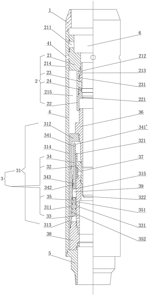
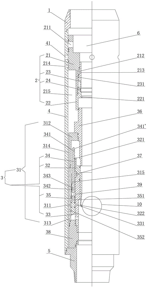
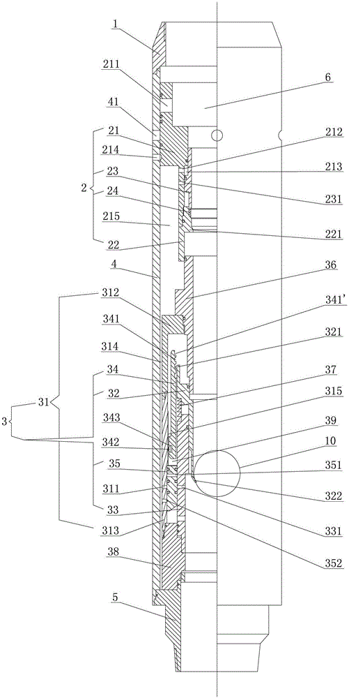
[0028] Such as figure 1 As shown, the present invention provides a reducing sleeve, which includes an upper joint 1 , a reducing mechanism 2 and a positioning mechanism 3 . Wherein, the lower end of the upper joint 1 is connected with a jacket 4, the lower end of the jacket 4 is connected with a lower connector 5, and the upper end of the jacket 4 is provided with a fracturing hole 41; The upper sliding sleeve 21 inside, the upper end of the upper sliding sleeve 2...


PUM


Abstract

The invention provides a hole shrinking sliding sleeve. The hole shrinking sliding sleeve comprises an upper connector, a hole shrinking mechanism and a positioning mechanism. The lower end of the upper connector is sequentially connected with an outer sleeve and a lower connector. The hole shrinking mechanism is provided with an upper sliding sleeve. The lower end of the upper sliding sleeve is connected with a lower sliding sleeve, a pushing rod penetrates through the upper sliding sleeve, and a retractable ball base is arranged between the pushing rod and the lower sliding sleeve in a clamping mode. The positioning mechanism is located below the hole shrinking mechanism, and is provided with a connecting barrel. A sliding barrel and a base penetrate through the connecting barrel, the sliding barrel axially and movably penetrates through the base, and a positioning rod and a piston are arranged between the base and the connecting barrel in a clamping mode. A plurality of clamping grooves are formed in the upper end of the positioning rod, the upper end of the sliding barrel is arranged inside the clamping grooves in a clamping mode, and the piston is connected to the connecting barrel. The hole shrinking sliding sleeve can be opened by putting steel balls with the same diameter, the opening of the hole shrinking sliding sleeve is not limited by the diameter of the put balls, the large drift diameter of a fractured tubular column is guaranteed, the number of the improved steps of oil layers is increased, and operating risks are reduced.

Description

technical field [0001] The invention relates to a ball-throwing sliding sleeve, in particular to a reducing sliding sleeve for downhole fracturing of an open-hole horizontal well in an oil field. Background technique [0002] At present, open-hole horizontal wells in oil fields mainly use "open hole packer + step-by-step ball-sliding sleeve" fracturing string for well completion and fracturing. The multi-stage ball-sliding sleeve used in this fracturing string has a The casing corresponds to the next oil layer in the well, and the inner diameter of the ball sliding sleeve corresponding to each oil layer becomes larger from bottom to top, and the opening and fracturing of each layer of the ball sliding sleeve are completed by dropping steel balls of different diameters from the wellhead. [0003] The size of the above-mentioned pitching sliding sleeve is limited by the size of the pitching ball. In order to meet the opening of the pitching sliding sleeve at different position...

Claims


Application Information

Patent Timeline
Patent Type & Authority Patents(China)
IPC IPC(8): E21B43/26
Inventor 裴晓含沈泽俊张国文钱杰王新忠李明
Owner PETROCHINA CO LTD
Why Eureka
Try Eureka