Corrosion control method for annular space tubing and casings of oil field water injection well

An annular space and corrosion control technology, used in chemical instruments and methods, earth-moving drilling, wellbore/well components, etc., can solve problems such as corrosion and perforation of water injection well tubing, inability to inject sewage, and casing strength reduction, and achieve control The reproduction of bacteria and the corrosion of the medium, the protection from corrosion, the effect of good stability

Inactive Publication Date: 2013-11-27
XI'AN PETROLEUM UNIVERSITY
View PDF3 Cites 13 Cited by
  • Summary
  • Abstract
  • Description
  • Claims
  • Application Information

AI Technical Summary

Problems solved by technology

During the water injection process of the water injection well, since the annular space of the water injection well is a dead water area, its environment is especially suitable for the growth of bacteria. The bacteria will continue to multiply and multiply in the annular space, and the hydrogen sulfide content in the annular space medium will increase significantly. Iron sulfide deposits and scales are produced on the wall, coupled with the high salinity of the medium in the annular space and the low pH value, the synergistic effect of multiple factors leads to serious uniform corrosion of the medium in the annular space, and severe pitting corrosion under the scale, resulting in serious corrosion of the oil pipe of the water injection well. 1. The casing has corrosion and perforation, sewage cannot be injected into the designed water injection layer, and water injection fails, especially the casing becomes thinner due to corrosion, corrosion produces grooves, the strength of the casing decreases, and it cannot bear the effect of ground stress and is deformed or broken. Water injection wells cannot be injected and are scrapped. New wells or casing repairs are required for re-injection, which is expensive and affects production. Moreover, the current casing repair technology is not perfect, and the cost is high but the success rate is low.

Method used


Image

  • Corrosion control method for annular space tubing and casings of oil field water injection well

Examples


Embodiment 1

[0021] This embodiment is a water injection well (well depth 2200m) with recovery water pipeline.

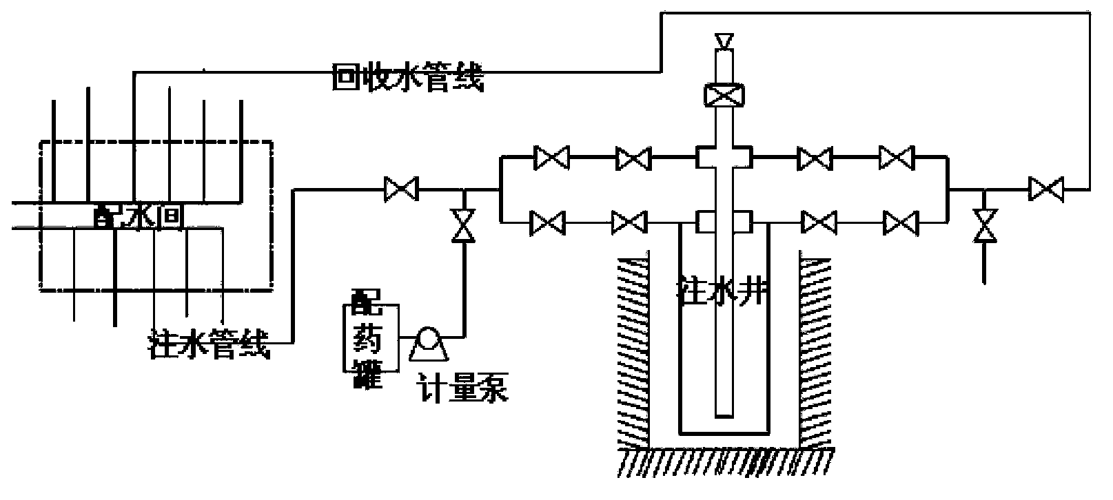
[0022] The construction process of this embodiment, the steps are: the connection process shown in Figure 1, the original water injection process at the wellhead of the water injection well is adjusted to the backwashing well process, the recovery water single well pipeline valve in the water distribution room is opened, and the well flushing displacement is adjusted to 25m 3 / h, after 1.5 hours of well flushing, reduce the flushing displacement to 10m 3 / h, start the high-pressure plunger metering pump to match the displacement of well flushing water, and add the A agent formula, add the mass concentration as 25%, and add the time for 2.1 hours, then reduce the plunger pump displacement to make the A agent add the mass concentration as 5%, the addition time is 4 hours, stop the plunger pump dosing, increase the flushing water discharge to 25m 3 / h, after 1.56 hours of well flu...

Embodiment 2

[0027] This embodiment is a water injection well (well depth 1800m) with a recovery water pipeline.

[0028] The construction process of this embodiment, the steps are: the connection process shown in Figure 1, the original water injection process at the wellhead of the water injection well is adjusted to the backwashing well process, the recovery water single well pipeline valve in the water distribution room is opened, and the well flushing displacement is adjusted to 25m 3 / h, after 1.5 hours of well flushing, reduce the flushing displacement to 10m 3 / h, start the high-pressure plunger metering pump to match the displacement of well-washing water, and add the A agent formula, add the mass concentration to be 25%, and the addition time is 1.72 hours, then reduce the plunger pump displacement to make the A agent add the mass concentration to be 5%, the addition time is 4 hours, stop the plunger pump dosing, increase the flushing water discharge to 25m 3 / h, after 1.36 hours...

Embodiment 3

[0033] This embodiment is a water injection well (well depth 2480m) with recovery water pipeline.

[0034] The construction process of this embodiment, the steps are: the connection process shown in Figure 1, the original water injection process at the wellhead of the water injection well is adjusted to the backwashing well process, the recovery water single well pipeline valve in the water distribution room is opened, and the well flushing displacement is adjusted to 25m 3 / h, after 1.5 hours of well flushing, reduce the flushing displacement to 10m 3 / h, start the high-pressure plunger metering pump to match the displacement of well flushing water, and add the A agent formula, add the mass concentration to be 25%, and the addition time is 2.4 hours, then reduce the plunger pump displacement to make the A agent add the mass concentration as 5%, the addition time is 4 hours, stop the plunger pump dosing, increase the flushing water discharge to 25m 3 / h, after 1.7 hours of we...


PUM

PropertyMeasurementUnit
corrosion rateaaaaaaaaaa

Abstract

Disclosed is a corrosion control method for annular space tubing and casings of an oil field water injection well. A construction technology comprises the steps of cleaning dirt on walls of the annular space tubing and casings up by an A agent or B agent formula, then, feeding a corrosion control treating agent with a certain concentration into annular spaces, and cleaning the annular spaces again and replacing the corrosion control treating agent after a period to protect the walls of the tubing and casings against corrosion for a long time. According to the corrosion control method, corrosion of annular space media to the tubing and the casings is reduced substantially, service lives (life)of the tubing and the casings of the water injection well can be prolonged by more than one time, the cost is low, the construction technology is simple and convenient, and effective technical support is provided for high yield and stable yield of oil fields.

Description

technical field [0001] The invention relates to an oil field casing pipe corrosion control technology, in particular to a method for controlling oil field casing pipe corrosion in an oil field water injection well annular space developed for corrosion of oil pipes and casing pipes in an annular space during the water injection process of an oil field water injection well. Background technique [0002] The oilfield has entered the middle and late stages of development. On the one hand, due to continuous development, the pressure of oil wells has dropped significantly, and the elastic recovery energy of oil layers has decreased. On the other hand, the water content in oil well output fluids has increased. The separated sewage is treated up to the standard, and the treated sewage is injected into the oil layer through the water injection well to achieve the purpose of maintaining the pressure of the oil layer and flooding crude oil with water. During the water injection process...

Claims


Application Information

Patent Timeline
Patent Type & Authority Applications(China)
IPC IPC(8): E21B37/06E21B37/00C09K8/528C09K8/54
Inventor 王相增郭学辉杜素珍刘立陶红胜李国明余海棠白李李磊
Owner XI'AN PETROLEUM UNIVERSITY
Why Eureka
Try Eureka