
Piston type pneumatic control valve

An air-controlled valve, piston-type technology, applied in the direction of hydraulic brake transmission, etc., can solve the problems of affecting the service life of the air-controlled valve, easy to increase the failure of moving parts, and complex structure of the moving unit.

Active Publication Date: 2013-11-27
ZHEJIANG RUILI AIR COMPRESSOR EQUIP CO LTD
View PDF12 Cites 7 Cited by
  • Summary
  • Abstract
  • Description
  • Claims
  • Application Information

AI Technical Summary

Problems solved by technology

This utility model only solves the problem of inconvenient installation of the air control valve existing in the prior art, and its motion unit structure is relatively complicated. Closed, its technical defects are: on the one hand, this structure is prone to motion accumulation errors, which in turn affects transmission efficiency; on the other hand, it is also easy to increase the probability of failure of moving parts, thus affecting the service life of the air control valve itself

Method used


Image

  • Piston type pneumatic control valve
  • Piston type pneumatic control valve
  • Piston type pneumatic control valve

Examples


Embodiment 1

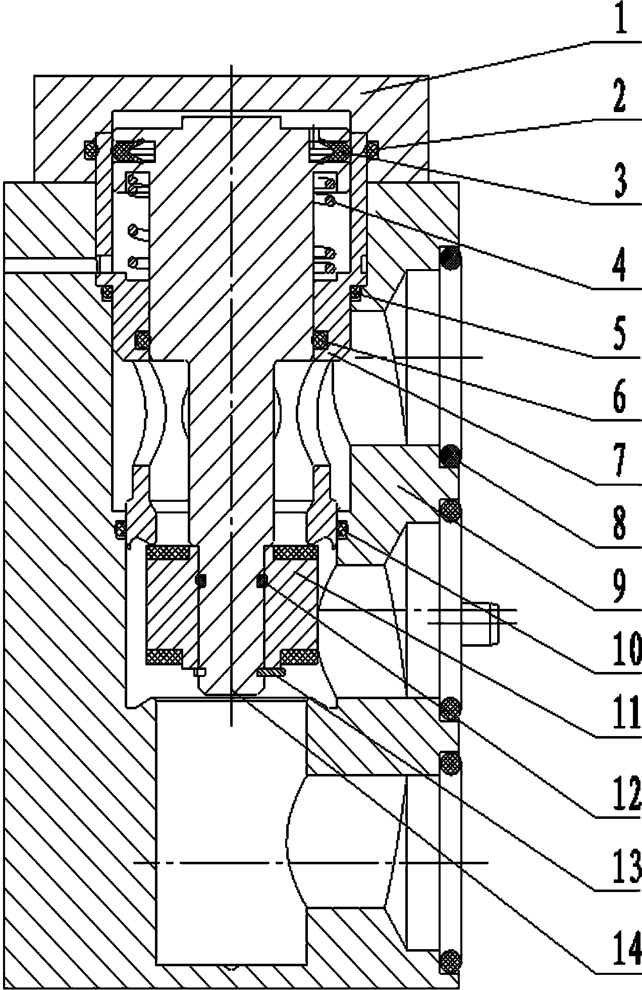
[0136] like Figure 1-6 As shown, a piston-type air control valve includes a valve body 9 with a stepped blind hole, the hole is equipped with a valve seat 7, the valve seat 7 is equipped with a valve stem 14, and the valve stem 14 is provided with a sealing ring groove. A K-shaped sealing ring 3 is installed in the sealing ring groove to realize the sealing at the sealing surface A between the valve seat 7 and the valve stem 14. The right end surface of the valve body 9 is respectively provided with an input port A1, an output port A2 and an exhaust port. Port A3, the stepped blind hole communicates with the input port A1, the output port A2 and the exhaust port A3 respectively, and the valve seat 7 is also installed on it, and the valve vulcanization assembly 11 is installed on the lower part of the valve stem 14, which includes an aluminum block and rubber The upper and lower surfaces of the aluminum block are respectively provided with boss planes, and the rubber parts are...

Embodiment 2

[0142] A piston type air control valve, similar to Embodiment 1, the difference is that the screw 16 is an American screw.

Embodiment 3

[0144] A piston type air control valve, similar to Embodiment 1, the difference is that the screw 16 is an inch screw.


PUM


Abstract

The invention discloses a piston type pneumatic control valve. The piston type pneumatic control valve comprises a valve body, wherein the valve body is provided with step blind holes and is internally provided with a valve seat; the valve seat is internally provided with a valve rod; the valve rod is provided with a sealing ring groove which is internally provided with a K-shaped sealing ring to realize sealing between the valve seat and the valve rod; an air inlet cavity is formed between the upper surface of the valve rod and the inner surface of a valve cover; the stressing area of the air inlet cavity to the upper end surface of the valve rod is larger than that of an input port to the lower end surface of the valve rod. Due to the structure, the working air pressure for enabling the valve rod to move downwards is low, and due to low air pressure, and the friction force and the wearing to the valve rod are reduced, so that the service life of a moving part is greatly prolonged. The piston type pneumatic control valve is mainly used for braking systems of railway vehicles, can realize connection and disconnection of the pipeline by fine adjustment to the air inlet pressure of a control port, and has the advantages of simple structure, reliable sealing and stable working performance; According to the technical scheme disclosed by the invention, all sealing pieces are respectively made of materials with high-temperature resistance and low-temperature resistance, and the requirement on long-time and normal use of the railway vehicles under the condition of severe environment can be met.

Description

technical field [0001] The invention relates to a valve, in particular to a piston type air control valve. Background technique [0002] The Chinese Utility Model Patent No. ZL201220257446.9 discloses an air-operated valve, the purpose of which is to provide an air-operated valve with a rotatable control part. The air-operated valve includes a valve body and a cylinder. The valve body is respectively provided with an inlet, an outlet, and a movable spool. A slidable piston is arranged in the cylinder. The piston rod that closes the channel between the inlet and the outlet, and the air control interface is provided on the outer wall of the cylinder, and it is characterized in that: a spacer is set between the cylinder and the piston rod, and one side of the spacer is fixed to the valve body connected, and the other side of the spacer is rotatably connected with the cylinder. The beneficial effect of the utility model is that: the cylinder part can be rotated, the installati...

Claims


Application Information

Patent Timeline
IPC IPC(8): B60T11/28
Inventor 李庆宣刘昕张玄李传武
Owner ZHEJIANG RUILI AIR COMPRESSOR EQUIP CO LTD
Learn More