Polarizer peeling machine and peeling method

A polarizer and peeling machine technology, applied in chemical instruments and methods, optics, nonlinear optics, etc., can solve the problems of inability to continuously peel off polarizers, low efficiency, harm to glass substrate circuits and operators, and improve Stripping efficiency, process saving, and easy stripping effect

Active Publication Date: 2013-11-27
BOE TECH GRP CO LTD +1
View PDF3 Cites 21 Cited by
  • Summary
  • Abstract
  • Description
  • Claims
  • Application Information

AI Technical Summary

Problems solved by technology

[0004] The existing polarizer peeling machine adopts a single roller system, and the polarizer peeling operation cannot be continuously performed during the operation process, and its efficiency is low, such as figure 1 As shown, the liquid crystal panel 1 is carried by two platforms 3, and the front section of the polarizer 2 will be raised with a blade, and the raised front section is connected with the single roller 4, and the polarizer 2 is peeled off by the single roller 4
Moreover, during the peeling process of the polarizer and the glass substrate, the glass substrate slides on the operating platform, and a large amount of static electricity will be accumulated due to friction, which will cause great harm to the circuits on the glass substrate and operators

Method used


Image

  • Polarizer peeling machine and peeling method
  • Polarizer peeling machine and peeling method
  • Polarizer peeling machine and peeling method

Examples


Embodiment Construction

[0029] The specific implementation manners of the present invention will be further described in detail below in conjunction with the accompanying drawings and embodiments. The following examples are used to illustrate and explain the technical solutions of the present invention, but are not intended to limit the scope of the present invention.

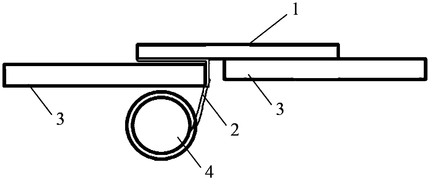
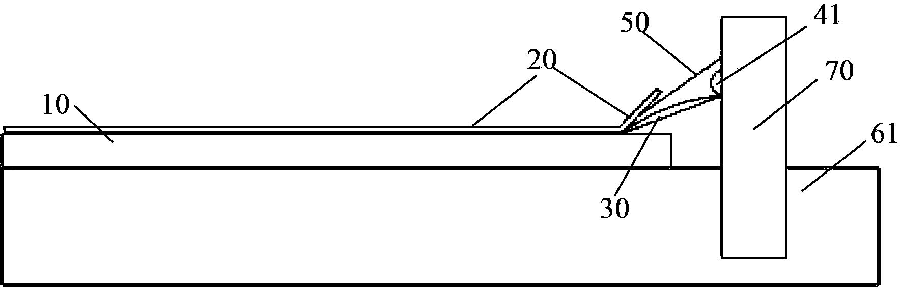
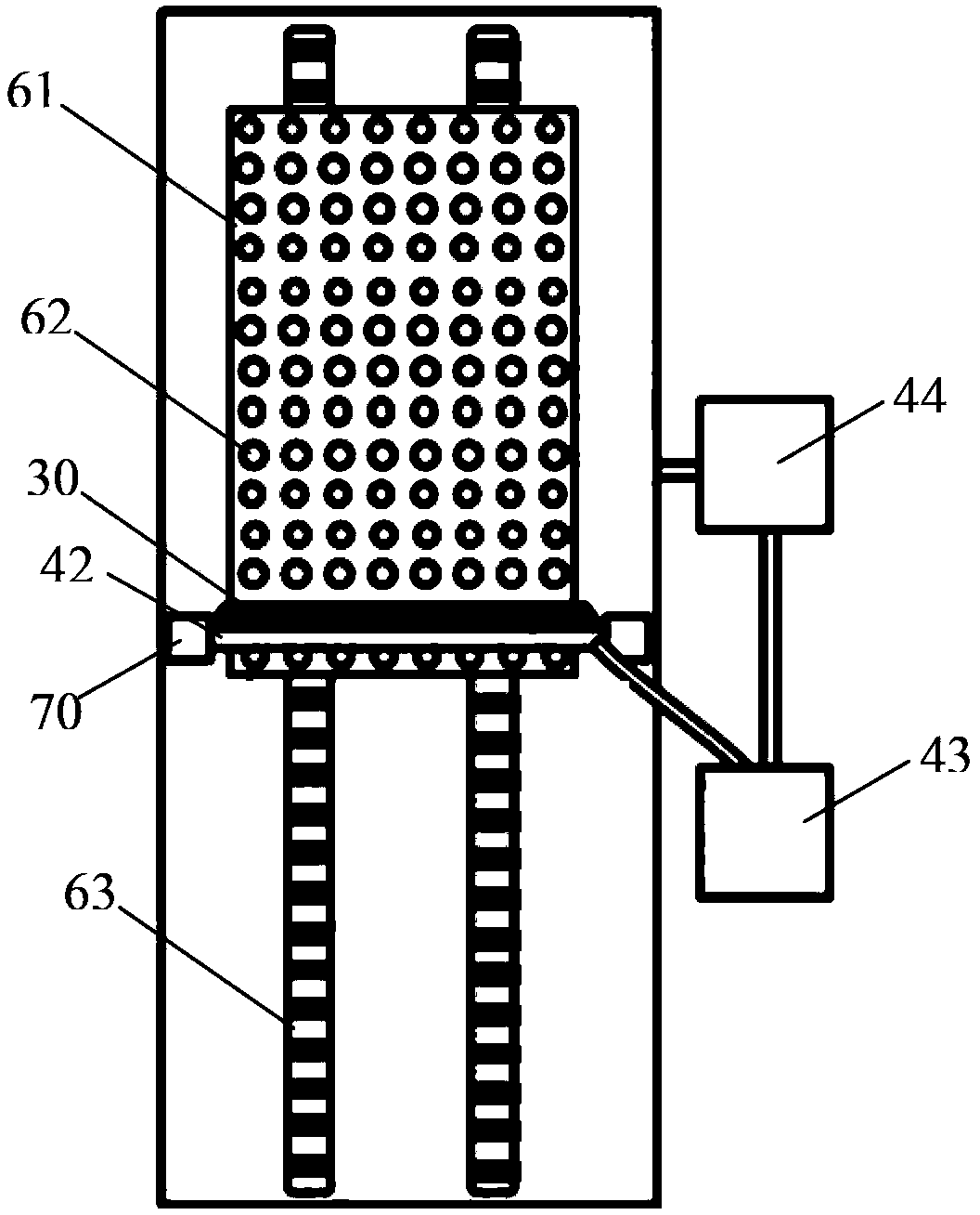
[0030] Such as figure 2 with 3 As shown, a polarizer peeling machine of the present invention includes a peeling blade 30 and a liquid medicine system, the peeling blade 30 is used to peel off the polarizer 20, the liquid medicine system includes a liquid spray nozzle 41, and the peeling blade 30 is used to peel off the polarizer 20. 20 is peeled off, the chemical liquid spray head 41 sprays the adhesive remover between the polarizer 20 and the liquid crystal panel 10 . Preferably, the stripping blade 41 is arranged obliquely so that the liquid medicine can flow between the polarizer 20 and the liquid crystal panel 10 along the sur...


PUM


Abstract

The invention relates to the technical field of thin-film transistor liquid crystal display, and discloses a polarizer peeling machine and a polarizer peeling method. The peeling machine comprises a peeling blade and an agent system. The peeling blade is used for peeling the polarizer. The agent system comprises an agent nozzle. When the peeling blade peels the polarizer, the agent nozzle sprays an adhesive remover between the polarizer and the liquid crystal surface plate. Two ends of the blade of the peeling blade are arc. The agent nozzle is positioned above the peeling blade. According to the invention, when the polarizer is peeled, the adhesive remover is sprayed, such that the adhesive between the polarizer and the liquid crystal surface plate can be removed, and the adhesion effect between the polarizer and the liquid crystal surface plate fails. Therefore, the polarizer can be easily peeled, and peeling effect can be improved. Also, with the adhesive remover, static electricity can be eliminated, such that safety of operators and circuit devices can be ensured.

Description

technical field [0001] The invention relates to the technical field of liquid crystal display, in particular to a polarizer peeling machine and a peeling method. Background technique [0002] In the TFT-LCD (Thin Film Transistor Liquid Crystal Display) preparation process, the attachment effect of the polarizer has an important impact on the display effect of the LCD (Liquid Crystal Display), and the attachment accuracy is not enough. If there are bubbles and scratches on the polarizer, etc. It is necessary to peel off the attached polarizer from the liquid crystal panel and attach it again to meet the quality requirements of the product. [0003] The existing method of peeling off the polarizer is: first use a blade to cut into the joint seam between the polarizer and the glass substrate of the liquid crystal panel to lift the front section of the polarizer, and then pull the raised front section of the polarizer until the polarizer is separated from the glass substrate . ...

Claims


Application Information

Patent Timeline
IPC IPC(8): B32B38/10G02F1/1335
CPCB32B38/10B32B2310/0418B32B2457/20G02F1/1303G02F1/133528
Inventor 梁魁
Owner BOE TECH GRP CO LTD
Why Eureka
Try Eureka