Eureka AIR delivers breakthrough ideas for toughest innovation challenges, trusted by R&D personnel around the world.

Double helix light beam-based sample axial drift detection and compensation method and device

A drift detection and compensation method technology, applied in optics, optical components, microscopes, etc., can solve the problems of system debugging and complex operation, and achieve the effect of easy construction and simple operation

Inactive Publication Date: 2013-11-20
ZHEJIANG UNIV
View PDF3 Cites 13 Cited by
  • Summary
  • Abstract
  • Description
  • Claims
  • Application Information

AI Technical Summary

Problems solved by technology

However, the current optical-based sample axial compensation methods are mostly based on confocal systems. Although they have good measurement accuracy, the debugging and operation of the system are relatively complicated, which limits the practical application of these methods to a certain extent.

Method used


Image

  • Double helix light beam-based sample axial drift detection and compensation method and device
  • Double helix light beam-based sample axial drift detection and compensation method and device
  • Double helix light beam-based sample axial drift detection and compensation method and device

Examples


Embodiment Construction

[0051] The present invention will be described in detail below in conjunction with the embodiments and accompanying drawings, but the present invention is not limited thereto.

[0052] Such as figure 1 As shown, a sample axial drift detection and compensation device based on a double helical beam, including: a laser 1, a single-mode fiber 2, a collimator lens 3, a mirror 4, a spatial light modulator 5, a beam splitting prism 6, a microscope Objective lens 7, three-dimensional nano-scanning platform 8, field lens 9, photoelectric sensing device 10, computer 11.

[0053]Among them, the single-mode optical fiber 2, the collimating lens 3, the reflector 4, the spatial light modulator 5, the beam splitting prism 6, the microscopic objective lens 7 and the three-dimensional nano-scanning platform 8 are sequentially located on the optical axis of the outgoing light path of the laser 1, showing The micro-objective lens 7 focuses the light onto the sample to be measured located on the...


PUM


Abstract

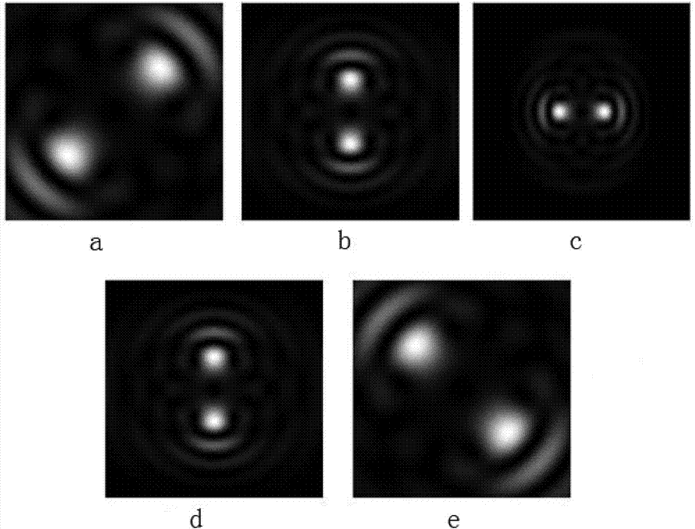
The invention discloses a double helix light beam-based sample axial drift detection and compensation method. The method comprises the following steps: performing phase modulation on a collimated laser beam to obtain a double helix illuminating light beam and projecting to a sample to be detected on a three-dimensional nano scanning platform to obtain a reflected light beam; focusing the reflected light beam into a focusing spot with two intensity peak values; receiving the focusing spot by using a photoelectric induction device to obtain spot intensity distribution information; calculating an included angle between a connecting line of the two intensity peak values and the horizontal direction according to the spot intensity distribution information; establishing a calibration function by using the relation of the included angle and axial drift of the sample; when the sample to be detected drifts in axial position, obtaining the axial drift of the current sample according to the calibration function by using the included angle measured in real time and then adjusting the axial position of the three-dimensional nano scanning platform to finish correction of the axial position of the sample to be detected. The invention also discloses a double helix light beam-based sample axial drift detection and compensation device.

Description

technical field [0001] The invention belongs to the field of high-precision and super-resolution microscopy, in particular to a method and device for real-time detection and compensation of sample axial drift based on double helical light beams. Background technique [0002] Due to thermal drift, stress drift and other factors, the position of the sample to be tested in the super-resolution microscopy system will inevitably drift in the axial direction, resulting in defocusing and affecting the accuracy of microscopic imaging. For microscopy methods that require repeated imaging of the same sample surface (such as super-resolution microscopy based on single-molecule localization), the effect of this axial drift will be more pronounced because the axial drift It is not the same sample face that will result in multiple repeated imaging. Therefore, a method that can detect and compensate the axial position drift of the sample in real time has very important application value i...

Claims


Application Information

Patent Timeline
IPC IPC(8): G02B27/30G02B21/00
Inventor 匡翠方李帅杨硕刘旭
Owner ZHEJIANG UNIV
Why Eureka
Eureka Blog
Learn More