Bus current detection method and current transformer equipment based on adjustable optical attenuator
A technology of dimming attenuation and bus current, applied in the direction of measuring current/voltage, voltage/current isolation, instruments, etc., can solve the problems of high power consumption, unstable measurement, etc., reduce power supply demand, eliminate optical attenuation constant drift, The effect of eliminating distractions
- Summary
- Abstract
- Description
- Claims
- Application Information
AI Technical Summary
Problems solved by technology
Method used
Image
Examples
Embodiment 1
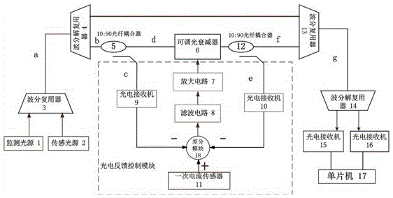
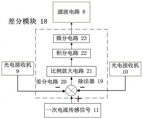
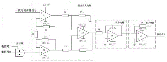
[0019] refer to figure 1, a bus current detection method based on an adjustable optical attenuator. The monitoring light and the sensing light are respectively generated by the monitoring light source 1 and the sensing light source 2. The sensing light is photoelectrically converted after passing through the adjustable optical attenuator 6. At the same time, Use the first optical fiber coupler 5 and the second optical fiber coupler 12 to respectively collect the input optical signal and output optical signal of the adjustable optical attenuator 6 and perform photoelectric conversion on the input optical signal and output optical signal, and use the primary current sensor 11 to obtain the high-voltage line The current signal of the bus on the bus and generate a current sensing signal, and then perform differential calculations on the primary current sensing signal and the input optical signal and output optical signal after photoelectric conversion, refer to figure 2 The obtai...
Embodiment 2
[0021] refer to figure 1 , a current transformer device, comprising: a monitoring light source 1, a sensing light source 2, a first wavelength division multiplexer 3, a first wavelength division multiplexer 4, an adjustable optical attenuator 6, a second wavelength division multiplexer 13, the second wave division multiplexer 14, the third photoelectric receiver 15, the fourth photoelectric receiver 16, the single chip microcomputer 17 and the photoelectric feedback control module, the monitoring light source 1 and the sensing light source 2 are respectively connected with the first wave division The two input terminals of the multiplexer 3 are connected, the output terminal of the first wavelength division multiplexer 3 is connected with the input terminal of the first wavelength division multiplexer 4, and an output terminal of the first wavelength division multiplexer 4 is connected with the second wavelength division multiplexer 4. An input end of the wavelength division m...
PUM
 Abstract
Description
Claims
Application Information
 - R&D
- Intellectual Property
- Life Sciences
- Materials
- Tech Scout
- Unparalleled Data Quality
- Higher Quality Content
- 60% Fewer Hallucinations
Browse by: Latest US Patents, China's latest patents, Technical Efficacy Thesaurus, Application Domain, Technology Topic, Popular Technical Reports.
© 2025 PatSnap. All rights reserved.Legal|Privacy policy|Modern Slavery Act Transparency Statement|Sitemap|About US| Contact US: help@patsnap.com


