
Patsnap Eureka
For R&D, Patsnap Eureka makes reading and utilizing patents & technical documents easy.
Patsnap Eureka AIR
Designed for self-driven R&D workflows. Generate viable solutions, solve complex R&D challenges, empower your innovation with AI.

Patsnap Eureka Materials
Designed for material experts only. Revolutionize your material R&D, from search, analyze, to developing new materials.

TechResearch
Generate reliable direction feasibility study reports for your R&D in just a few steps.

TechSeek
Discover and master advanced knowledge NOW. Basics, ideas, possibilities, all at once.

TechMind
As an expert in R&D Theories, TechMind can generates customized viable solutions instantly.

TechRisk
Analyze your overall solution with one click, know your potential R&D risks in advance.

TechMonitor
Get weekly tech updates, stay abreast of the latest tech innovations and key insights.
Pneumatic expansion type clamp
A pneumatic expansion clamp technology, which is applied in the field of machining fixtures, can solve the problems of prolonging the processing cycle, long processing auxiliary time, and increasing processing costs, and achieve the goal of increasing the length of the force arm, convenient and quick clamping, and improving processing accuracy. Effect
- Summary
- Abstract
- Description
- Claims
- Application Information
AI Technical Summary
Problems solved by technology
Method used
Image

Examples
Embodiment Construction
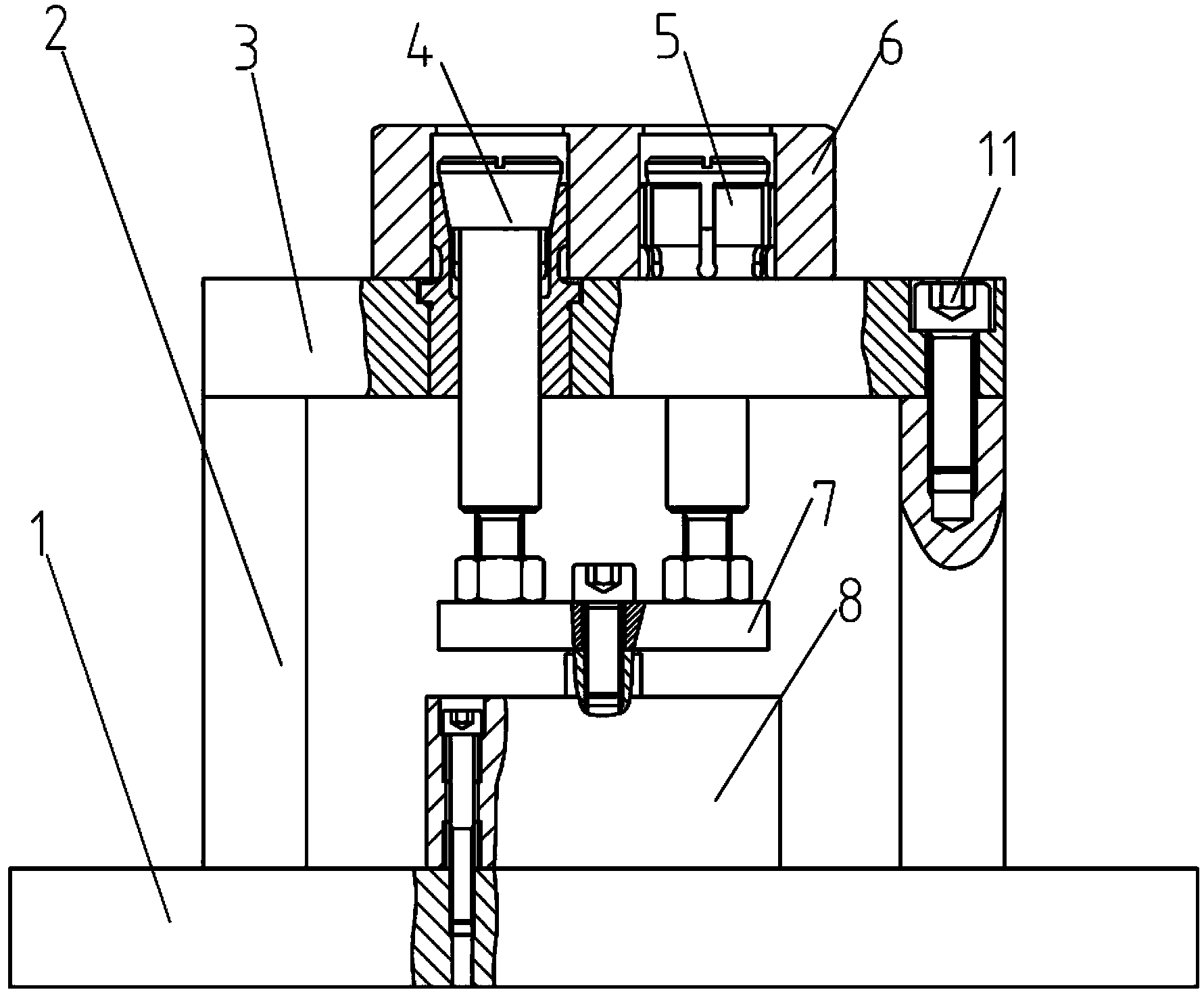
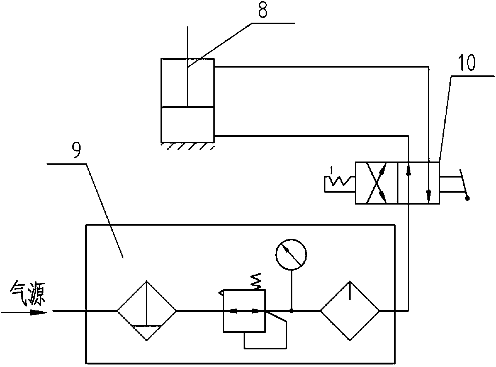
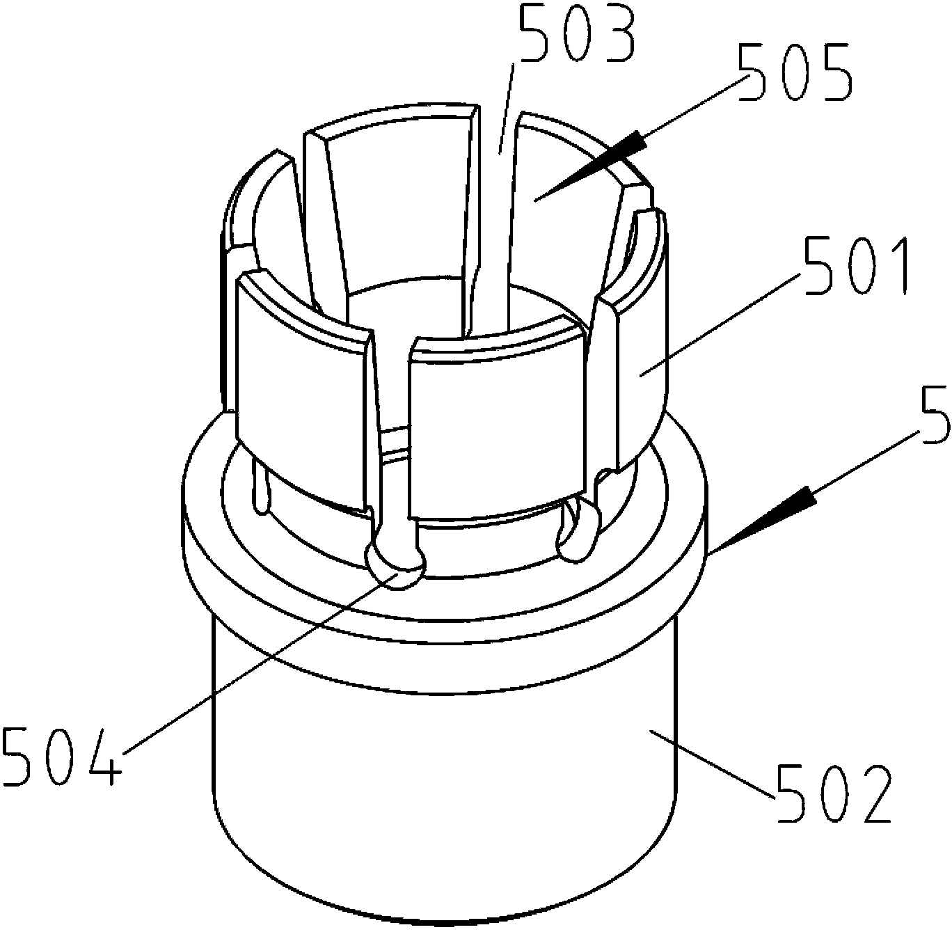
[0021] See attached figure 1 ~ Attached Image 6 The pneumatic expansion clamp includes a bottom plate 1, two support plates 2, a positioning plate 3, a tie rod 4, an expansion sleeve 5, a cross rod 7 and a cylinder 8; the two support plates 2 stand on the bottom plate 1 respectively On both sides of the top surface, the positioning plate 3 is located at the top end of the two supporting plates 2 and is fixedly connected with the two supporting plates 2; the positioning plate 3 is provided with a hole penetrating the positioning plate 3 The pull rod 4 and the expansion sleeve 5; the lower end of the pull rod 4 and the lower end of the expansion sleeve 5 are both fixedly connected to the cross rod 7, and the cross rod 7 is opposite to the piston of the cylinder 8. Fixed connection.
[0022] The top end of the support plate 2 is provided with a screw hole, the positioning plate 3 is provided with a through hole that penetrates the positioning plate 3 along the thickness direction ...
PUM
 Abstract
Description
Claims
Application Information
 - R&D Engineer
- R&D Manager
- IP Professional
- Industry Leading Data Capabilities
- Powerful AI technology
- Patent DNA Extraction
Browse by: Latest US Patents, China's latest patents, Technical Efficacy Thesaurus, Application Domain, Technology Topic, Popular Technical Reports.
© 2024 PatSnap. All rights reserved.Legal|Privacy policy|Modern Slavery Act Transparency Statement|Sitemap|About US| Contact US: help@patsnap.com