LED (Light Emitting Diode) filament support series connection forming method based on support material plate
A technology of LED filament and support material plate, applied in the field of lighting, can solve the problems of many solder joints, production efficiency needs to be improved, multi-manpower, etc., and achieve the effect of reducing welding time, reducing production cost, and improving production efficiency
- Summary
- Abstract
- Description
- Claims
- Application Information
AI Technical Summary
Problems solved by technology
Method used
Image

Examples
Embodiment 1
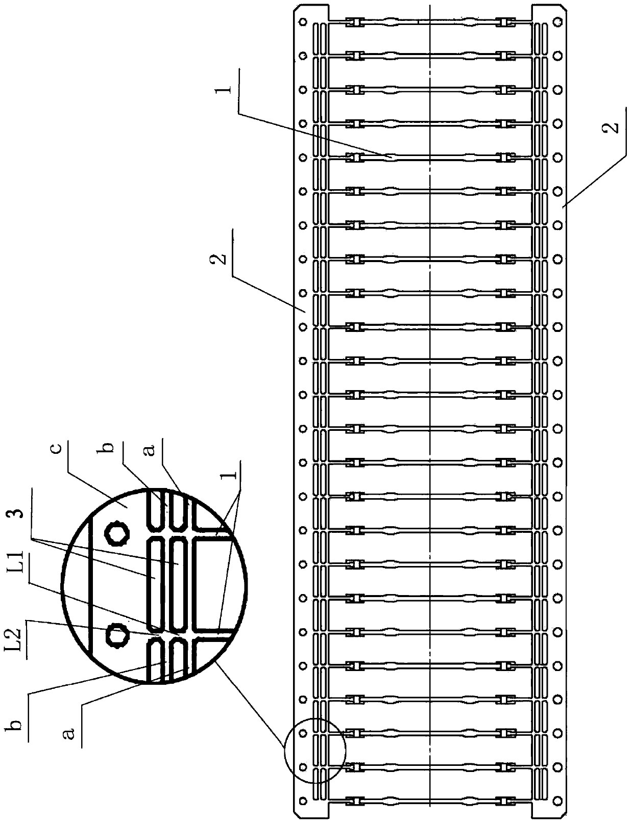
[0064] Described LED filament support tandem forming method comprises the following steps:
[0065] Ⅰ. Cutting off all the inner extensions in the connecting parts of the upper side and the lower side, at this time, all the middle connecting edges, outer connecting edges and outer extending sections of each connecting part are cut off and separated;
[0066] Ⅱ. Cut off the inner connecting edge with an even number in the connecting part on the upper side; such as No. 2 inner connecting edge, No. 4 inner connecting edge, No. 6 inner connecting edge, etc.;
[0067] Ⅲ. Cut off the inner connecting edge with an odd number in the connecting part of the lower side; such as the inner connecting edge of No. 1, the inner connecting edge of No. 3, and the inner connecting edge of No. 5;
[0068] The above steps can be carried out simultaneously or step by step, which is determined according to the needs.
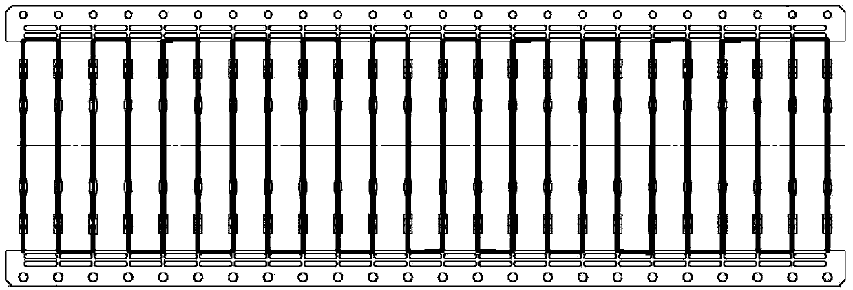
[0069] Such as figure 2 As shown, the bold part is the structure reserved o...
Embodiment 2
[0071] Described LED filament support tandem forming method comprises the following steps:
[0072] Ⅰ. Cutting off all the outer extensions in the connecting portion of the upper side and the lower side, at this time all the outer connecting edges are also cut off and separated;
[0073] Ⅱ. Cutting off the inner connection edge and the middle connection edge whose sequence number is an integral multiple of 4 in the connection portion on the upper side;
[0074] Ⅲ. Cut off the inner connecting edge with an odd number in the connecting part on the upper side;
[0075] IV. Cut off the inner extensions with serial numbers 2, 6, 10... in the connecting part on the upper side, and the tolerance of serial numbers between the cut inner extensions is 4;
[0076] V. Cut off the inner extensions with serial numbers 3, 7, 11... in the connecting part on the upper side, and the tolerance of serial numbers between the cut inner extensions is 4;
[0077] VI. Cut off the inner connect...
Embodiment 3
[0084] The LED filament support tandem forming method comprises the following steps:
[0085] Ⅰ. Cutting off all the outer extensions in the connecting portion of the upper side and the lower side, at this time, the outer connecting edge is also cut off and separated;
[0086] Ⅱ. Cut off the inner extension with an even number in the connection part on the upper side;
[0087] Ⅲ. Cutting off all inner connection edges in the connection part on the upper side;
[0088] IV. Cut off the inner extension with an odd number in the connection part on the lower side;
[0089] V. Cut off all the inner connecting edges in the connecting part of the lower side;
[0090] The above steps can be carried out simultaneously or step by step, which is determined according to the needs.
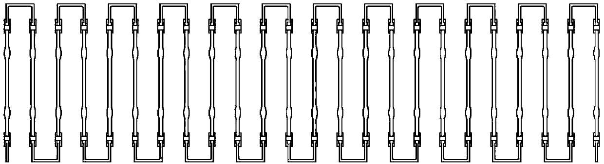
[0091] Such as Image 6 As shown, the bold part is the structure reserved on the support material plate. After the cutting work is completed, the following Figure 7 Two sets of LED filament holders i...
PUM
 Abstract
Description
Claims
Application Information
 - R&D
- Intellectual Property
- Life Sciences
- Materials
- Tech Scout
- Unparalleled Data Quality
- Higher Quality Content
- 60% Fewer Hallucinations
Browse by: Latest US Patents, China's latest patents, Technical Efficacy Thesaurus, Application Domain, Technology Topic, Popular Technical Reports.
© 2025 PatSnap. All rights reserved.Legal|Privacy policy|Modern Slavery Act Transparency Statement|Sitemap|About US| Contact US: help@patsnap.com