Sensing element with unevenly distributed magnet sheets in shell

A technology of evenly distributed, sensing elements, applied in vehicle components, instruments, speed/acceleration/shock measurement, etc., can solve the problems of different, easily damaged permanent magnet blocks, inconsistencies, etc.

Active Publication Date: 2013-11-06
江苏鸿迅机车有限公司
View PDF8 Cites 0 Cited by
  • Summary
  • Abstract
  • Description
  • Claims
  • Application Information

AI Technical Summary

Problems solved by technology

[0013] Disadvantages (1) Using two permanent magnets with no difference to represent the fixed positions of the two pedals, only multiple Halls can be used to represent the pedals Rotation position: There is no difference between the two permanent magnets. The advantage is that the fixed positions of the two pedals can be expressed regardless of the left and right feet, so that the left and right feet can generate power assistance requirements, which can produce the same motor power assistance effect; but the disadvantage is that The permanent magnetic steel itself cannot indicate the rotation position of the pedal, but can only use multiple Halls at different corner positions to indicate the rotation position of the pedal, so it is not possible to use only one Hall, but must use multiple Halls
[0014] Disadvantage (2) Only one Hall cannot be used, and three Halls will inevitably cause the original segmentation error of the three control signals, which will distort the power-assist demand model, naturally The generation of power output is inconsistent with the demand for power assistance: no matter whether the power-assisted bicycle has one or two motors, the sensor signal for controlling the motor can only be controlled by using one sensor signal input to the motor controller; and the patent uses three sensors. If Hall controls the motor, the three control signals of the three Halls must be combined into one combined control signal before it can be input to the motor controller
The sensing parameters of the three Halls cannot be the same, especially due to changes in ambient temperature and long-term use, the sensing parameters of the three Halls may vary greatly. The output voltages are different, resulting in different power output of the motor, and the power output is inconsistent with the power demand; similarly, when the power demand is the same, the outputs of different Halls may be the same voltage, resulting in the same power output of the motor, and also There is a problem that the power output is inconsistent with the power demand
[0015] Disadvantages (3) The combined control signal is prone to signal drift, which makes the combined control signal not match the motor controller, and the power-assisted demand model is distorted: due to changes in ambient temperature and use time After a long period of time, the sensing parameters of the three Halls may vary greatly, and the connection points of the three control signals of the three Halls will inevitably change, so the combined control signals generated by the same boosting demand will produce segmental signal drift. Combining the control signals as a whole produces signal distortion, that is, the power-assist demand model is distorted, causing the motor controller to choose any one of the three control signals as a reference, which will cause the problem that the power-assisted output is inconsistent with the power-assisted demand
[0016] Disadvantage (4) The sensing points cannot be increased arbitrarily. If there are too few sensing points, the motor will not run smoothly, making the rider feel very uncomfortable: due to the disadvantages (1) and (2) are the most important The number of halls is greater than one. Obviously, the more the number of halls, the more serious the shortcomings (1) and (2) are.
Therefore, the power-assisted bicycle provided by this patent can only be a very bad power-assisted bicycle that makes the rider feel comfortable.
[0017] Disadvantages (5) The signal blind area reaches 42 degrees, and when the power is needed when starting, it is impossible to get it: as we all know, the moment of a person pedaling on a bicycle is the smallest at the apex , from the angle of 10-45 degrees away from the top is the area that needs the most assistance, but the angle between the Halls in this patent is 42.5-43.5 degrees, and there is no Hall in the area of ​​10-42 degrees away from the top of the pedal. There is no control signal, and the result is when the assist is most needed, but the motor of the assist bicycle cannot assist
[0018] In short, this patent is a technical solution for using multiple Halls to control the booster mode, because only multiple Halls can be used to represent the rotation position of the pedal, and the multiple control signals of multiple Halls must have original errors, and the combined control signals It is also easy to produce signal drift, which can cause distortion of the assist demand model, that is, the same assist demand at different times, but different assist effects; the more the number of Halls, the more serious the distortion of the assist demand model, limiting the number of Halls , a small amount of Hall will cause the motor to run unsteadily, making the rider feel very uncomfortable, and will not get assistance when starting
To make it undistorted to help the demand model, and to ensure the smooth operation of the motor, there are always two issues. It is impossible to have both.
[0019]International patent application WO / 099 / 13558AI discloses a sensor for controlling the motor on the motor, the sensor is provided with a depression on the rotating disk, and the permanent magnet block is snapped into the In the depression of the rotating disk, this process drills the depression on the rotating disk, and can only manually insert multiple permanent magnet blocks into the depression of the rotating disk one by one, which is very time-consuming and labor-intensive. The size and shape of the permanent magnet must fit well, which is difficult to achieve
Because the sag is too large for the permanent magnet block, the permanent magnet block vibrates in the sag when the rotating disc rotates, and the permanent magnet block is easily damaged; the sag is tightly matched with the permanent magnet block, and it is difficult to snap the permanent magnet block into the rotating disc. in the depression
The international patent application WO / 099 / 13558AI does not disclose the setting structure of the Hall, let alone the problem of adjusting the Hall to adjust the sensing model

Method used


Image

  • Sensing element with unevenly distributed magnet sheets in shell
  • Sensing element with unevenly distributed magnet sheets in shell
  • Sensing element with unevenly distributed magnet sheets in shell

Examples


Embodiment 1

[0060] Example 1. Sensing element with evenly distributed multi-magnetic sheets in a polyurethane-cast housing for holding magnetic sheet layers

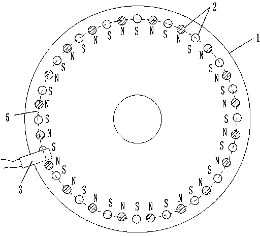
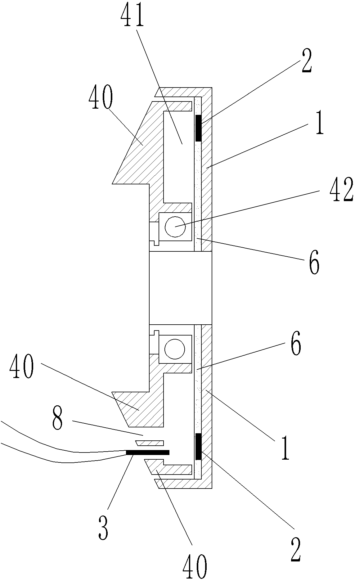
[0061] Such as figure 1 , 3 , With an annular groove rotating disc 1 and an annular groove fixing disc 40 with opposite concave surfaces, the size of the annular groove rotating disc 1 and the annular groove fixing disc 40 is just such that the annular groove fixing disc 40 can fit in Annular groove rotating disc 1 in the annular groove, the two discs can be relatively rotatable fitting inner hollow shell, the concave surface of the two discs sandwiched into a hollow ring 41; the ring groove rotating disc at the position of the hollow ring 41 20 permanent magnet pieces 2 are pasted and fixed on 1. On the surface of the annular groove rotating disc 1 with the permanent magnet sheet 2 and the surface of the permanent magnet sheet 2, there is also a pinching magnetic sheet layer 6. The permanent magnet sheet 2 is clamped and fixed between...

Embodiment 2

[0070] Embodiment 2. Sensing element with uniform distribution of multiple magnetic sheets in a high-density housing

[0071] Such as figure 2 , 3 , The annular groove rotating disc 1 in the hollow ring 41 has a diameter of 10.0 cm, and 40 permanent magnet pieces 2 are arranged on the annular groove rotating disc 1. The 40 permanent magnet pieces 2 each have a diameter of 0.6 cm. The thickness is 0.2mm, and the magnetic flux is 146---279(B·H)max / KJ·m -3 One of the values ​​in. The Hall 3 maintains an interval of 0.2 cm from each permanent magnet plate 2 in the rotating state, so that when each rotating permanent magnet plate 2 passes through the Hall 3, the Hall 3 can generate a corresponding rectangular wave electrical signal output. The structure of other rotating disk 1, permanent magnet plate 2, and Hall 3 is the same as that of the first embodiment.

Embodiment 3

[0072] Embodiment 3. A sensor element with evenly distributed multiple magnetic sheets in the housing of the aluminum plate for holding the magnetic sheet layer

[0073] Such as figure 1 , 3 , With an annular groove rotating disc 1 and an annular groove fixing disc 40 with opposite concave surfaces, the size of the annular groove rotating disc 1 and the annular groove fixing disc 40 is just such that the annular groove fixing disc 40 can fit in Annular groove rotating disc 1 in the annular groove, the two discs can be relatively rotatable fitting inner hollow shell, the concave surface of the two discs sandwiched into a hollow ring 41; the ring groove rotating disc at the position of the hollow ring 41 20 permanent magnet pieces 2 are pasted and fixed on 1. On the surface of the annular groove rotating disc 1 with the permanent magnet sheet 2 and the surface of the permanent magnet sheet 2, there is also a pinching magnetic sheet layer 6. The permanent magnet sheet 2 is clamped a...


PUM

PropertyMeasurementUnit
thicknessaaaaaaaaaa
thicknessaaaaaaaaaa
thicknessaaaaaaaaaa

Abstract

The invention discloses a sensing element with a plurality of magnet blocks uniformly distributed in a housing, belongs to the technical field of signal providing magnetic induction, and particularly relates to a technology for providing a control signal with multi-point magnetic induction on a rotating component. A plurality of permanent magnets and Halls are arranged in cavities embedded in a rotation plate and a fixed plate; the permanent magnets are fixedly arranged on the rotation plate and distributed to form a ring-shaped structure in such a manner that the adjacent magnetic polarities of the permanent magnets are opposite, that is, the distribution manner is N pole, S pole, N pole and so on; and the Halls on the fixed plate are arranged in positions near the permanent magnets. The sensing element has the advantages that as the adjacent magnetic polarities of the permanent magnets are opposite, that is, the distribution manner is N pole, S pole, N pole and so on, the Halls can acquire rectangular wave signals, and digital processing can be conducted on the rectangular wave signals conveniently; and the positions of the permanent magnets and the Halls are fixed relatively, so that signals can be output reliably.

Description

Technical field [0001] The present invention belongs to the technical field of magnetic induction to provide signals, and particularly relates to a technology for providing control signals through multi-point magnetic induction on a rotating component. Background technique [0002] The Chinese patent 201020295192.0 "hook-type torque sensor device" applied by Yebao Vehicle Material Industry (Kunshan) Co., Ltd. discloses a sensor device for a power-assisted bicycle. The sensor device includes a magnetic part and an elastic part to cooperate to sense the transmission of torque. 感装置。 The device. After a long time of use, the change of the elastic coefficient of the elastic member will cause the sensing signal and the control effect of the controlled motor to change, and the assisting effect will become incompatible with the person's assisting needs. Moreover, the design structure of the elastic piece is complicated and the manufacturing cost is high. [0003] The Chinese patent 012018...

Claims


Application Information

Patent Timeline
Patent Type & Authority Applications(China)
IPC IPC(8): B62M6/50G01L3/00G01P3/481
Inventor 黄强
Owner 江苏鸿迅机车有限公司
Why Eureka
Try Eureka