
Pipe manipulation apparatus and method

A technology for pipe fittings and tubular components, which is applied in pipe fittings manipulating devices and fields, and can solve problems such as the reduced ability of tools to fully engage tubular parts and the inability to manipulate tubular parts, and achieve the effects of eliminating scratches or deformation, eliminating the need, and increasing safety

Inactive Publication Date: 2016-09-07
CANRIG DRILLING TECH
View PDF9 Cites 0 Cited by
  • Summary
  • Abstract
  • Description
  • Claims
  • Application Information

AI Technical Summary

Problems solved by technology

However, such tools are often incapable of manipulating tubular components of non-uniform size
The tool's ability to adequately engage the tubular component is reduced when the tubular component being manipulated is not of ideal size, for example by having varying wall thickness or imperfect cylindricity or circularity

Method used


Image

  • Pipe manipulation apparatus and method
  • Pipe manipulation apparatus and method
  • Pipe manipulation apparatus and method

Examples


Embodiment Construction

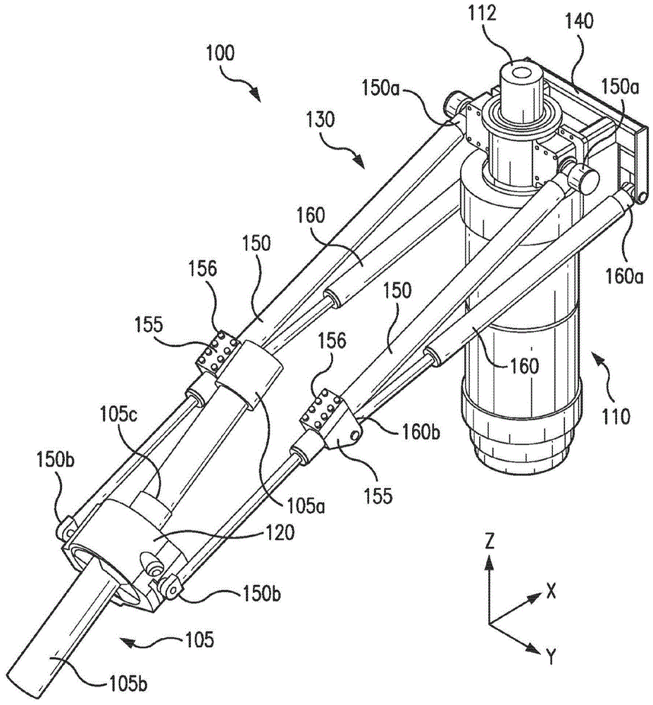
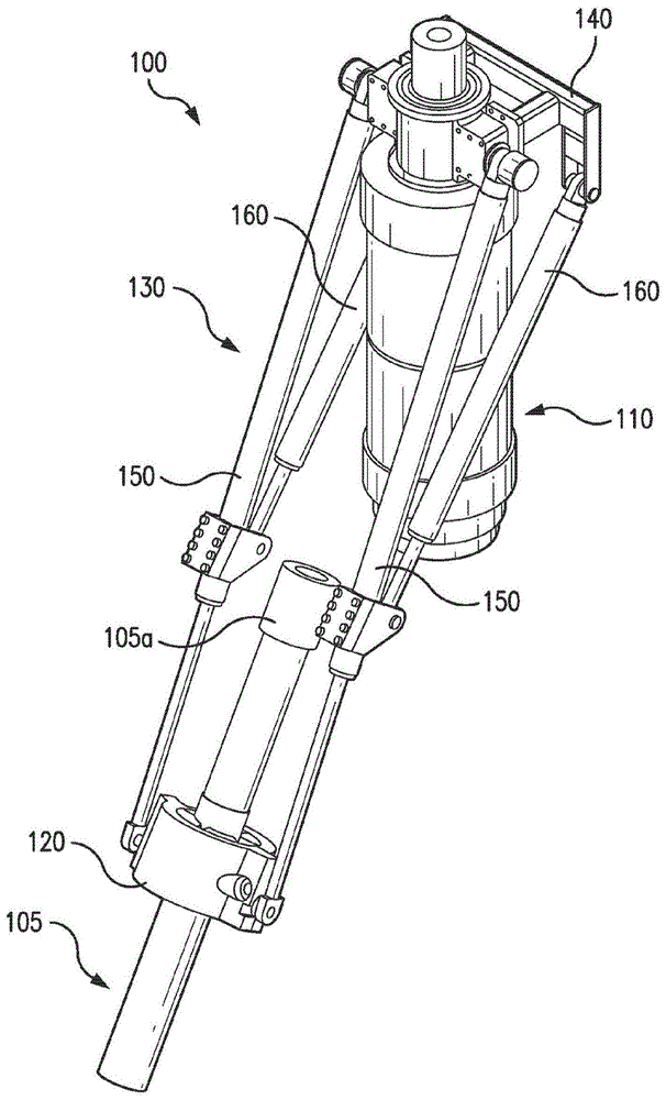
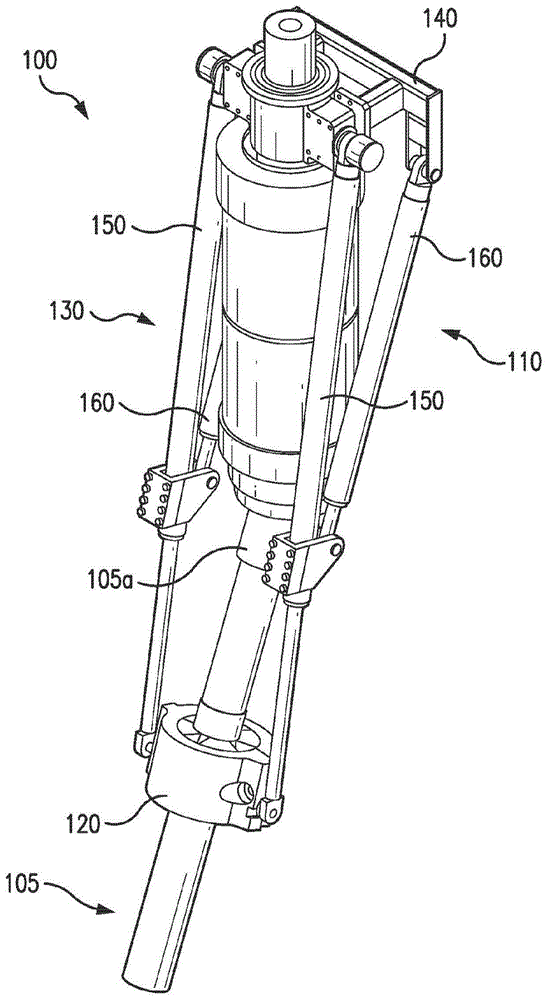
[0037] It should be understood that the following disclosure provides many different embodiments or examples for achieving the different features of various embodiments. Specific examples of components and arrangements are described below to simplify the present disclosure. Of course, these are examples only and are not intended to be limiting. In addition, the present invention may repeatedly refer to numbers and / or letters in various examples. This repetition is for brevity and clarity and does not inherently dictate the relationship between the various embodiments and / or configurations discussed. Also, in the ensuing description, forming a first feature over or on a second feature may include embodiments where the first and second features are formed in direct contact, and may also include embodiments in which additional features may be formed on the first feature. An embodiment in which the first feature and the second feature may not be in direct contact between a featu...


PUM


Abstract

A tubular handling apparatus including a tubular member running tool adapted to provide load-bearing, and preferably torquing, capacity upon the gripping of a tubular is provided. The running tool includes a slotted member having a plurality of elongated slots, a recessed member associated with the slotted member and having a plurality of recesses, and a plurality of gripping elements disposed between the slotted member and recessed member. Each such gripping element is adapted to move with an engaged tubular so as to grip the tubular. A tubular member elevator associated to the running tool, as well as related floor slips, are also encompassed. Methods of casing running are also included.

Description

Background technique [0001] Drilling of subterranean wells involves assembling tubular strings, such as casing strings and drill strings, each of which includes a plurality of heavy, elongated tubular sections that extend from the drilling rig down into the wellbore. The pipe string consists of a plurality of threaded joint pipe sections. [0002] Typically, workers use labor-intensive methods to join pipe sections to form pipe strings. This method involves the use of a worker, usually a "stabber" and multiple operators, such as a pliers operator. Sharps are placed in a raised position within the rig on the centralizing table to manually align individual pipe sections with the existing pipe string. This is an inherently unsafe location due to the height at which sharps are placed and the large number of moving parts within the rig. Various operators ensure the alignment and connection of individual pipe sections with existing pipe strings on the rig floor. The tong operato...

Claims


Application Information

Patent Timeline
Patent Type & Authority Patents(China)
IPC IPC(8): E21B19/06
CPCE21B19/06
Inventor 布赖恩·埃利斯费萨尔·J·优素福比特·屈特尔克雷格·文姆斯
Owner CANRIG DRILLING TECH
Learn More