
Constant-temperature stress corrosion testing device and method for FRP (fiber reinforced polymer) tendon

A stress corrosion and test device technology, applied in the direction of applying stable tension/pressure to test the strength of materials, can solve the problems of long test period, difficult to move, difficult to control constant temperature, etc., to achieve the effect of simple structure and convenient production

Inactive Publication Date: 2013-10-30
SOUTHEAST UNIV
View PDF7 Cites 38 Cited by
  • Summary
  • Abstract
  • Description
  • Claims
  • Application Information

AI Technical Summary

Problems solved by technology

At present, there are many studies on the durability of FRP bars directly immersed in corrosion solution, but the coupling between corrosion solution environment and stress is less due to the complexity of the test equipment, and this is the real state of FRP bars.
In the existing research, because the test device generally uses gravity to control the stress constant, through mechanical force transmission, the device is complex and bulky, not easy to move, and it is difficult to control the constant temperature, and temperature is an important factor affecting the corrosion rate of FRP bars
Generally, the number of reinforcements is large and the test period is long in the reinforcement corrosion test, so the device is required to be simple and portable

Method used


Image

  • Constant-temperature stress corrosion testing device and method for FRP (fiber reinforced polymer) tendon
  • Constant-temperature stress corrosion testing device and method for FRP (fiber reinforced polymer) tendon
  • Constant-temperature stress corrosion testing device and method for FRP (fiber reinforced polymer) tendon

Examples


Embodiment Construction

[0040] The present invention will be further described below in conjunction with the accompanying drawings.

[0041] see figure 1 , figure 2 , image 3 , Figure 4 and Figure 5 As shown, the FRP tendon constant temperature stress corrosion test device of the present invention includes a tension frame 1, a first threaded anchor 31, a second threaded anchor 32, a tee pipe 4, a spring 6, a third end plate 7, and a reaction frame 8. Jack 10, force sensor 11 and tension anchor 12.

[0042]Wherein, the tension frame 1 includes a support rod 111 , a first end plate 121 , a second end plate 122 and a reinforcing plate 13 . The tensioning frame 1 of the present invention is used to provide the reaction force during the tensioning process, and keep the stress level of the FRP tendon constant during the long-term test process, and has sufficient rigidity and bearing capacity. The tension frame 1 is made of steel, and each part is assembled by welding. The specific dimensions and ...


PUM


Abstract

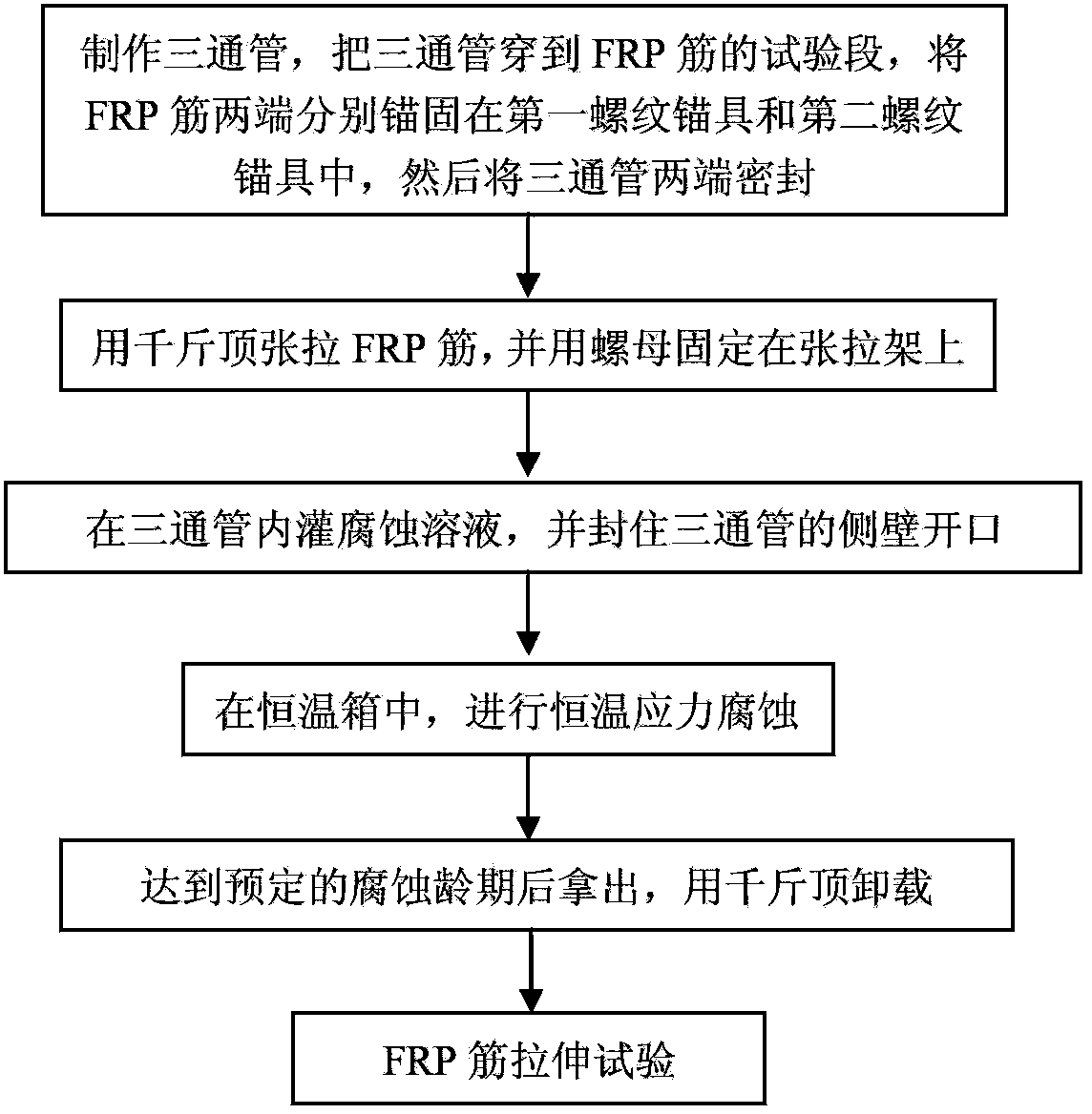
The invention discloses a constant-temperature stress corrosion testing device and method for an FRP (fiber reinforced polymer) tendon. The device comprises a stretch-draw frame, threaded anchors, a three-way pipe, a spring, a counter force frame, a lifting jack, a force sensor and a stretch-draw anchor rod. Certain stretch-draw stress is applied to the FRP tendon by utilizing the stretch-draw frame, the counter force frame, the lifting jack and the force sensor, and the FRP tendon is fixed by a nut, and the stress loss is compensated by the compression spring, and the constant stress level can be kept for a long time. A corrosion solution soaking environment is provided through a method that a corrosion solution is filled into a home-made PVC pipe device fixed in the middle of the FRP tendon, so that the FRP tendon is in the corrosion solution soaking environment for a long time. After the corrosion solution is filled completely and the prestress is stretched and drawn, the whole stretch-draw frame for stretching and drawing the FRP tendon is put into a constant-temperature constant-humidity test box so as to guarantee the long-term constant-temperature environment. After the constant-temperature corrosion, the device is unloaded through the steps the same with the stretch-draw step, the FRP tendon is taken down for a stretch test. The method comprises the following steps of: anchoring the FRP tendon, fixing through stretching and drawing, corroding at constant temperature, unloading and carrying out the stretch-draw test.

Description

technical field [0001] The invention belongs to the technical field of long-term mechanical performance test methods of composite materials, and in particular relates to a constant-temperature stress corrosion test device and method for FRP bars. Background technique [0002] Resin-based fiber reinforced composite material (Fiber Reinforced Polymer, referred to as FRP) is a high-performance material formed by mixing fiber material and matrix material in a certain proportion and compounding through a certain process. This material came out in the 1940s and was initially used in high-tech fields such as aviation, aerospace, and national defense. Later, it was widely used in automotive, chemical, and medical fields. In recent years, due to its high strength, light weight, corrosion resistance and other advantages, it has been widely used in civil engineering structures, and has attracted extensive attention from the engineering community. [0003] Due to its excellent corrosio...

Claims


Application Information

Patent Timeline
IPC IPC(8): G01N3/10
Inventor 吴刚
Owner SOUTHEAST UNIV
Learn More