electric vacuum cleaner
A vacuum cleaner, electric technology, applied in the direction of the suction filter, etc., can solve the problems of dust discharge, disposal difficulties, inability to increase the dust collection volume, and encourage dust, etc., to achieve easy dust discharge, increase the opening area, and increase the dust collection volume Effect
- Summary
- Abstract
- Description
- Claims
- Application Information
AI Technical Summary
Problems solved by technology
Method used
Image
Examples
Embodiment 1
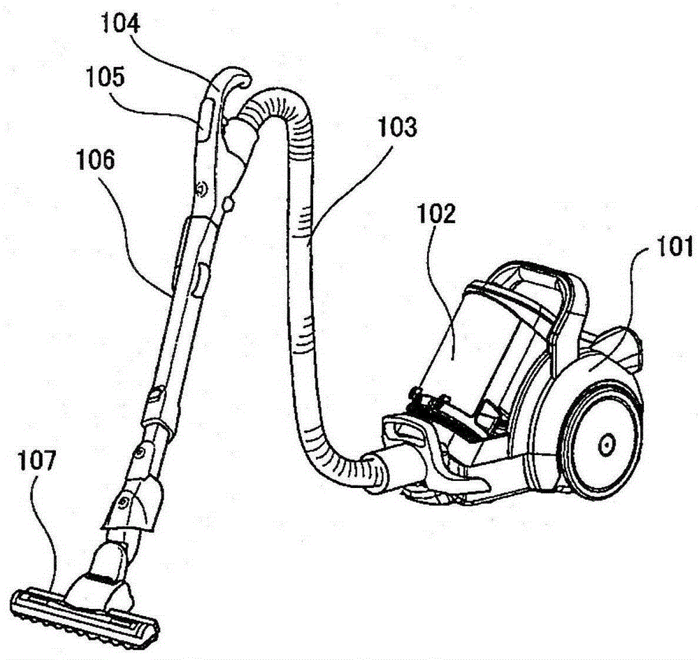
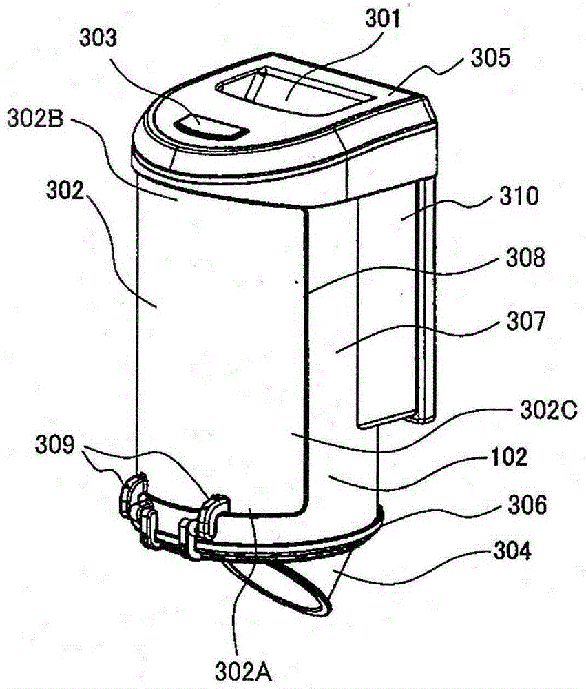
[0034] Hereinafter, a first embodiment of the present invention will be described in detail with reference to the drawings. figure 1 A perspective view showing the appearance of the electric vacuum cleaner used in the present invention, figure 1 Among them, symbol 101 is a vacuum cleaner main body, and a cyclone dust collector 102 is mounted on the vacuum cleaner main body 101. The vacuum cleaner main body 101 is connected to a hand handle 104 via a suction hose 103, and the hand handle 104 is connected to a suction mouth body 107 via an extension pipe 106.
[0035] And the handle 104 at hand is equipped with the operation part 105 at hand which controls the drive of the electric blower built in the cleaner main body 101, and the electric rotary brush provided in the nozzle body 107.
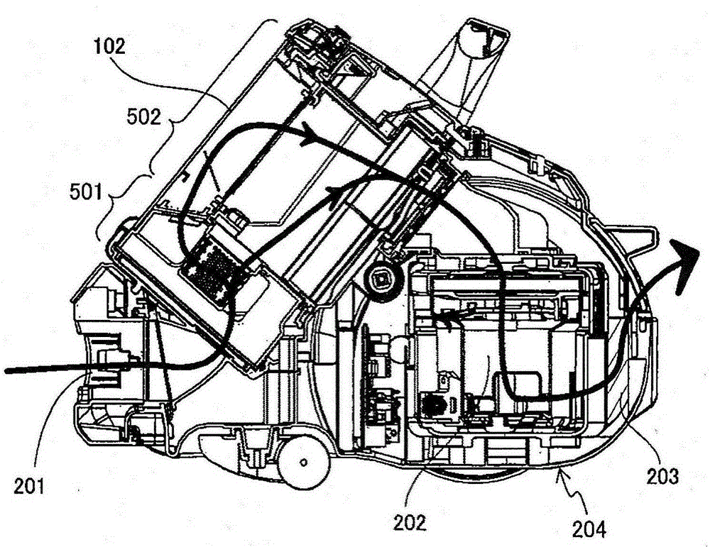
[0036] figure 2 Shows a cross-sectional view of the vacuum cleaner main body 101 cut approximately in the center, and a hose attachment port 201 is formed in a casing 204 of the vacuum cleaner...
Embodiment 2
[0094] Next, the second embodiment of the present invention will be described in detail with reference to the drawings. Since the main body of the vacuum cleaner basically has the same structure as that of the first embodiment, the dust collector will be described below.
[0095] Image 6 It shows the cross-sectional view which cut the cyclone type dust collector 601 which concerns on 2nd Embodiment of this invention substantially in the center.
[0096] Image 6 Among them, the dust collector 601 is composed of a cyclone separation unit 602 that separates dust and air by centrifugal force generated by rotating air containing dust, and a dust collection chamber 603 that stores separated dust.
[0097] As shown in the drawing, a dust collection chamber 603 for storing separated dust is disposed adjacent to the lower side of the cyclone separation unit 602 . The cyclone separation unit 602 and the dust collection chamber 603 are integrally formed so that they cannot be separat...
Embodiment 3
[0125] Next, the third embodiment of the present invention will be described in detail with reference to the drawings. Since the main body of the vacuum cleaner basically has the same structure as that of the first embodiment, the dust collector will be described below.
[0126] Figure 8 It shows the cross-sectional view which cut the cyclone type dust collector 801 which concerns on the 3rd Embodiment of this invention substantially in the center.
[0127] Figure 8 Among them, the dust collector 801 is composed of a cyclone separation unit 802 that separates dust and air by centrifugal force generated by rotating air containing dust, and a dust collection chamber 803 that stores separated dust.
[0128] As shown in the drawing, a dust collection chamber 803 for storing separated dust is arranged adjacent to the lower side of the cyclone separation unit 802 . The cyclone separation unit 802 and the dust collection chamber 803 are integrally formed so that they cannot be se...
PUM
 Abstract
Description
Claims
Application Information
 - R&D Engineer
- R&D Manager
- IP Professional
- Industry Leading Data Capabilities
- Powerful AI technology
- Patent DNA Extraction
Browse by: Latest US Patents, China's latest patents, Technical Efficacy Thesaurus, Application Domain, Technology Topic, Popular Technical Reports.
© 2024 PatSnap. All rights reserved.Legal|Privacy policy|Modern Slavery Act Transparency Statement|Sitemap|About US| Contact US: help@patsnap.com


