
Liquid-sealed antivibration device

A technology of anti-vibration device and liquid seal, applied in the direction of shock absorber, shock absorber-spring combination, spring, etc., to achieve the effect of inhibiting cavitation phenomenon, forming easy, and increasing the opening area

Active Publication Date: 2009-09-30
HONDA MOTOR CO LTD +1
View PDF3 Cites 29 Cited by
  • Summary
  • Abstract
  • Description
  • Claims
  • Application Information

AI Technical Summary

Problems solved by technology

[0010] However, it has been found that if such a movable membrane is used, the movable membrane rotates due to the continuous input of large-amplitude vibration, and if the position of the pressure relief valve and the leakage passage deviates, it will affect the prevention of cavitation, and it is required to prevent the movable membrane rotation

Method used


Image

  • Liquid-sealed antivibration device
  • Liquid-sealed antivibration device
  • Liquid-sealed antivibration device

Examples


Embodiment Construction

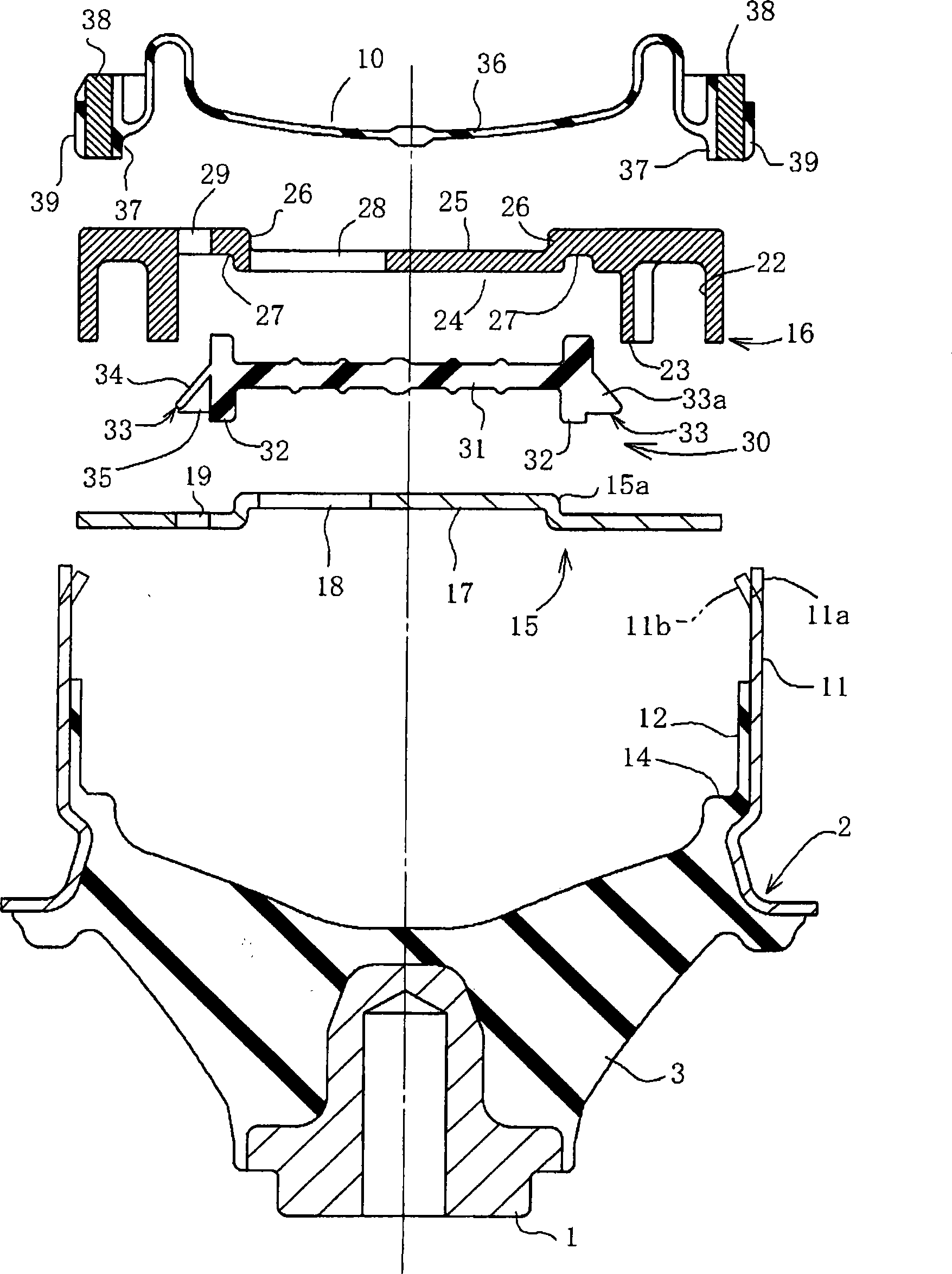
[0072] Next, an embodiment of an engine mount for an automobile will be described with reference to the drawings. figure 1 is the longitudinal sectional view of the engine bracket, figure 2 It is a figure which breaks down each constituent part. figure 1 It is also a section cut along the input direction Z of the main vibration. In addition, in the following description, each direction, such as up, down, left, and right, is based on the state shown in the figure which is the object of description.

[0073] In these figures, the engine mount includes a first mounting member 1 mounted on the side of the engine (not shown) as a vibration source, a second mounting member 2 mounted on the vehicle body (same as above) as a vibration receiving side, and a connection between them. Between the vibration isolator 3. The vibration isolator 3 is composed of a well-known elastic member for vibration isolation such as rubber, and is an elastic body serving as a vibration isolation main ...


PUM


Abstract

A relief valve having a structure where a cavitation phenomenon is prevented is simply and reliably operated. A thin center section (31) and a stationary section (32) are provided on an elastic diaphragm (30) placed inside a partition member (6), the stationary section (32) is fixed in position, and a relief valve (33) is formed integrally with the outer periphery of the stationary section (32). The relief valve (33) has a slope surface (34) on the auxiliary liquid chamber (7) side and also has a depression section (35) opened to the main liquid chamber (5) side. The rigidity of the relief valve (33) varies in the circumferential direction. When the pressure inside the main liquid chamber (5) is negative, operation liquid in the auxiliary liquid chamber (7) opens the relief valve (33) to leak it to the main liquid chamber (5), preventing occurrence of a cavitation phenomenon. Since the relief valve (33) is integrally formed with the elastic diaphragm (30), the relief valve for cavitation prevention can be easily produced, does not affect the existing structure, facilitates assembly and tuning, and can be realized at low cost. Antivibration performance is maintained constant without affecting performance of an orifice path.

Description

technical field [0001] The present invention relates to a liquid-seal anti-vibration device used for an engine bracket of an automobile, in particular to a liquid-seal anti-vibration device capable of effectively reducing abnormal noise caused by cavitation. Background technique [0002] In this type of liquid-sealed anti-vibration device, when a large load is input, the main liquid chamber may become negative pressure momentarily, because at this time, a part of the working fluid is vaporized, and cavitation occurs, accompanied by abnormal noise. Therefore, various proposals have been made to prevent transmission of the abnormal noise. [0003] As one of them, when the main liquid chamber becomes negative pressure, the main liquid chamber and the orifice passage are short-circuited to cause the hydraulic fluid to leak (see Patent Document 1). [0004] In addition, it is proposed to dispose the elastic film in the through hole of the partition member so that the outer perip...

Claims


Application Information

Patent Timeline
Patent Type & Authority Applications(China)
IPC IPC(8): F16F13/18F16F13/10
Inventor 久保信夫柳濑浩齐藤淳西坂真朋
Owner HONDA MOTOR CO LTD
Learn More