
Device and method for measuring performance parameters of traffic signal in visible light communication system

A visible light communication and traffic signal technology, which is applied in the field of measurement devices for traffic signal performance parameters, can solve the problems of not being able to clearly display the solar radiation noise and frequency response performance of the VLC system, and limit the transmission rate of input signals, so as to achieve good promotion and use The effect of value, low cost, and wide modulation bandwidth

Active Publication Date: 2013-10-23
深圳市莱法照明通信科技有限公司
View PDF4 Cites 3 Cited by
  • Summary
  • Abstract
  • Description
  • Claims
  • Application Information

AI Technical Summary

Problems solved by technology

On the other hand, due to the inherent photons generated by LED lights through recombination, and the interaction of parasitic capacitance and inductance of LED traffic lights, the radiated lights experience a transition period driven by the input current, or a limited Bandwidth, the occurrence of these phenomena will limit the transmission rate of the input signal, so in the VLC system, the measurement of the frequency response of LED traffic lights is an indispensable item in the design of the system transmission rate
But at present, researchers' research and exploration on outdoor VLC systems mainly focus on system design and simulation, and they are all based on a simplified ideal link model or an actual demonstration system with a specific receiving path. The two performances of solar radiation noise and frequency response of the VLC system in commercial off-the-shelf LED (COTS LED) lamps cannot be clearly shown, and thus cannot provide more reliable and comprehensive data analysis for the application of outdoor VLC technology to intelligent transportation

Method used


Image

  • Device and method for measuring performance parameters of traffic signal in visible light communication system
  • Device and method for measuring performance parameters of traffic signal in visible light communication system
  • Device and method for measuring performance parameters of traffic signal in visible light communication system

Examples


Embodiment Construction

[0037] The present invention will be further described below in conjunction with the accompanying drawings and embodiments.

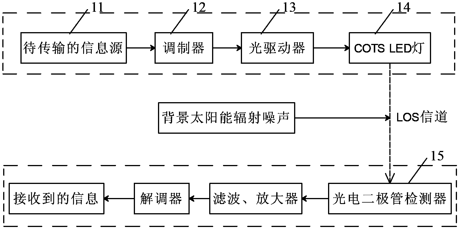
[0038] figure 1 A conventional outdoor VLC system based on a photodiode detector is shown. refer to figure 1 , the electrical signal sent from the information source 11 to be transmitted is input into the modulator 12, wherein the modulator 12 also includes a pulse shaper, and the modulated electrical signal is converted into an optical signal through the optical driver 13 and the LED lamp 14, Transmission in the LOS (Line of sight) channel, during transmission, the signal is interfered by the background environment (solar radiation noise), therefore, the signal output by the photodiode detector 15 needs to be filtered, amplified, and finally demodulated at the receiving end output the required information.

[0039] The present invention is designed for the application of this traditional outdoor VLC system based on photodiode detectors in ITS.

[0...


PUM


Abstract

The invention relates to a device and method for measuring performance parameters of traffic signals in a visible light communication system. A traffic signal emitter in the visible light communication system is an LED lamp. A traffic signal receiver is a photodiode detector. The measuring device comprises a first measuring model used for measuring radiation noise of solar energy and / or a second measuring model used for measuring the frequency response of the LED lamp. A measuring method based on any of the measuring models includes the following steps that the first measuring model is used for measuring radiation noise of the solar energy and / or the second measuring model is used for measuring the frequency response of the LED lamp. The device and method for measuring the performance parameters of the traffic signals in the visible light communication system can measure two performance parameters, namely radiation noise of the solar energy in a VLC system and the frequency response of the LED lamp.

Description

technical field [0001] The invention belongs to the technical field of communication, in particular to a device and method for measuring traffic signal performance parameters in a visible light communication system. Background technique [0002] Visible light communication (Visible light communication, VLC) uses LED (Light-emitting diode) lighting as the transmitter of its transmission, and has received attention in the field of optical wireless communication technology. Visible light communication technology uses the flickering of LED lamps that cannot be recognized by the naked eye to transmit "0" or "1" signals, which enables the signals to be fully modulated in a limited bandwidth, and compared with traditional lighting sources, LED lamps are less expensive to use Longer life, higher lighting efficiency, easier maintenance, smaller size, more energy saving and environmental protection. [0003] At present, research on applying outdoor VLC transmission technology to the ...

Claims


Application Information

Patent Timeline
Patent Type & Authority Applications(China)
IPC IPC(8): H04B10/07G01M11/02H04B10/116
Inventor 权进国金爽刘维浩
Owner 深圳市莱法照明通信科技有限公司
Learn More