
Thin-plate-type rotating ultrasonic motor

An ultrasonic motor and thin plate technology, applied in the direction of generators/motors, piezoelectric effect/electrostrictive or magnetostrictive motors, electrical components, etc., can solve the disadvantages of miniaturization, miniaturization, limited application range, and unfavorable design and processing problems, to achieve the effect of compact structure and simple driving circuit

Inactive Publication Date: 2013-10-23
吕晓威
View PDF0 Cites 5 Cited by
  • Summary
  • Abstract
  • Description
  • Claims
  • Application Information

AI Technical Summary

Problems solved by technology

But at the same time, it brings a new problem: the tooth groove increases the complexity of the stator, which is not conducive to design and processing; it is also not conducive to micro and miniaturization, and the application range is limited

Method used


Image

  • Thin-plate-type rotating ultrasonic motor
  • Thin-plate-type rotating ultrasonic motor
  • Thin-plate-type rotating ultrasonic motor

Examples


Embodiment Construction

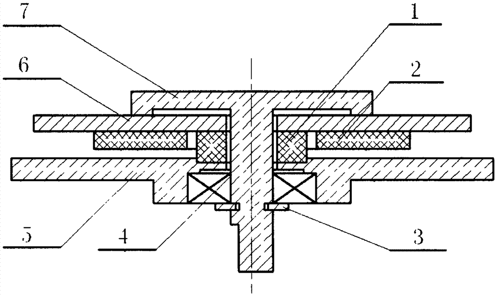
[0013] The working principle and specific implementation of the thin-plate double traveling wave rotary ultrasonic motor will be described below by taking the number of partitions of the fan-shaped silver-plated electrode 8 as 8 as an example.

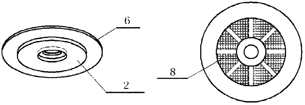
[0014] Such as figure 1 , figure 2 As shown, the thin-plate double traveling wave rotary ultrasonic motor of the present invention is mainly composed of a stator assembly, a rotor and a bracket assembly. The stator assembly adopts a composite structure of an annular thin metal sheet 6 and an annular piezoelectric ceramic sheet 2 . The piezoelectric ceramic ring is unidirectionally polarized and has eight evenly partitioned fan-shaped silver-plated electrodes 8; the rotor 7 and the base 5 are positioned by the bearing 4; the rubber spring 1 is pressed between the stator and the base 5 to fix the stator and provide a , The pre-pressure between the rotors. The thin-plate double-traveling-wave rotary ultrasonic motor of the present inv...


PUM


Abstract

The invention discloses a thin-plate-type rotating ultrasonic motor which belongs to the field of ultrasonic motors. The motor comprises a rotor, a base, a bearing, a rubber spring and a stator. The rotor and the base are positioned through the bearing; the rubber spring is pressed between the stator and the base for fixing the stator and providing a pre-pressure between the stator and the rotor at the same time; the stator adopts a composite structure of an annular metal thin sheet and an annular piezoelectric ceramic plate; and the piezoelectric ceramic plate is one-way polarized and is provided with fan-shaped silvered electrodes which are uniformly sectioned. Compared to traditional wave-type ultrasonic motors, the thin-plate-type rotating ultrasonic motor is simple in structure, low in manufacturing cost, easy to miniaturize, and applicable to precision mechanical devices and optical apparatuses.

Description

Technical field: [0001] The invention relates to a thin-plate rotary ultrasonic motor. Background technique: [0002] Ultrasonic motor is a kind of inverse piezoelectric effect of piezoelectric material, which excites the elastic body to generate micro-vibration in the ultrasonic frequency band, and converts it into the rotary (linear) motion of the rotor (mover) through the friction between the stator and the rotor. new motors. Among them, the basic principle of the traveling-wave rotary ultrasonic motor is to form an elliptical motion on the surface of the stator by exciting the traveling wave of the bending vibration (or out-of-plane vibration) on the ring or the disc. The length of the tangential axis of the trajectory ellipse is not only proportional to the length of the normal axis, but also proportional to the thickness of the stator. The longer the tangential axis of the ellipse, the higher the motor speed, and vice versa. However, the stator bending vibration ampl...

Claims


Application Information

Patent Timeline
IPC IPC(8): H02N2/10H02N2/12
Inventor 吕晓威
Owner 吕晓威
Learn More