
Circuit breaker

A circuit breaker, high-voltage circuit breaker technology, applied in the direction of high-voltage air circuit breakers, circuits, high-voltage/high-current switches, etc., can solve the problems of slow mechanical contact actuation and/or arc extinguishing performance, complex settings, etc., to achieve reliable Effect of electrical connection, fast response time

Inactive Publication Date: 2013-10-23
ABB TECH AG
View PDF7 Cites 1 Cited by
  • Summary
  • Abstract
  • Description
  • Claims
  • Application Information

AI Technical Summary

Problems solved by technology

[0006] However, the disclosed devices and / or methods have the disadvantage that they are rather complex to set up and / or they exhibit rather slow mechanical contact actuation and / or arc extinguishing performance

Method used


Image

  • Circuit breaker
  • Circuit breaker
  • Circuit breaker

Examples


Embodiment Construction

[0038] Description of the figure:

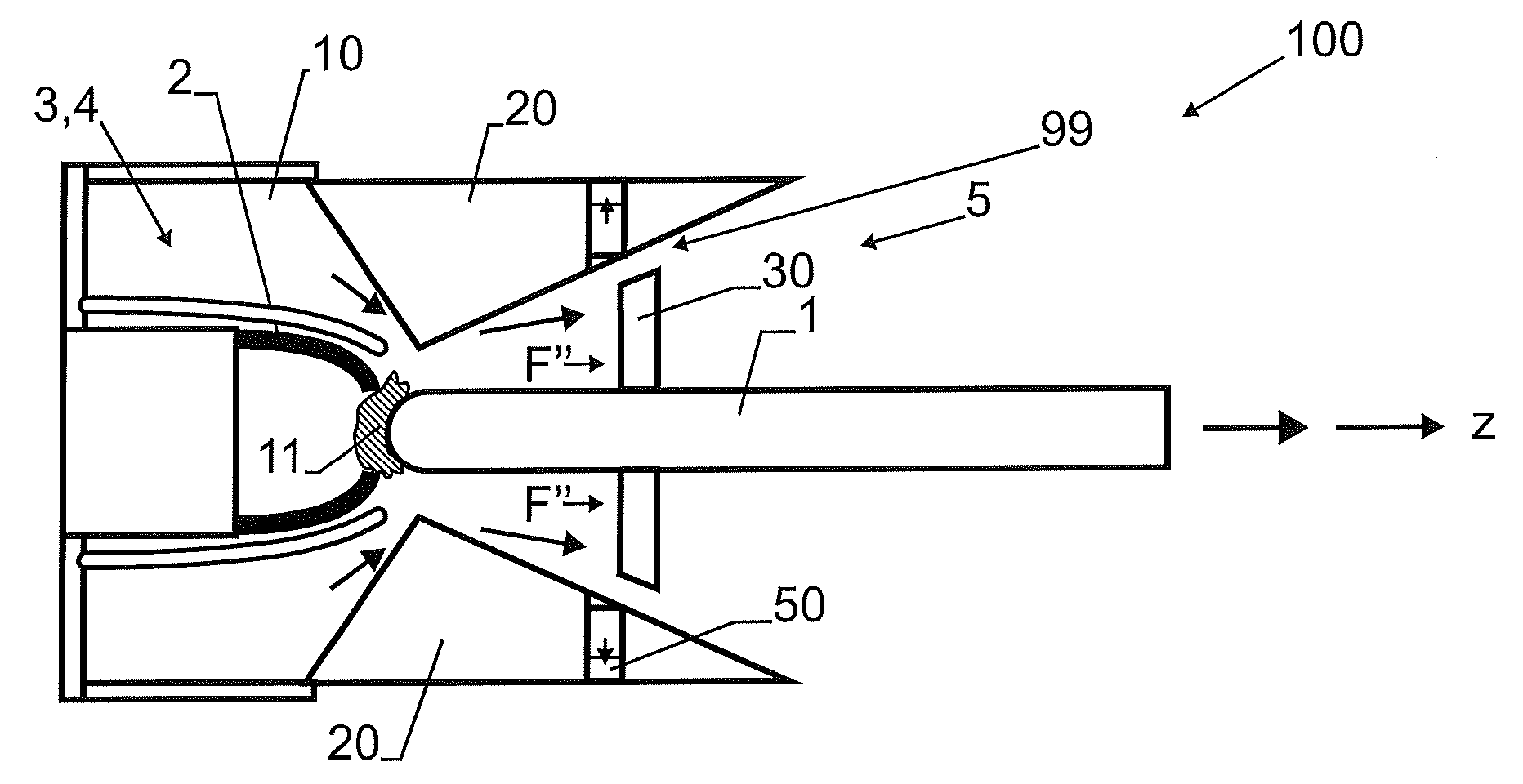
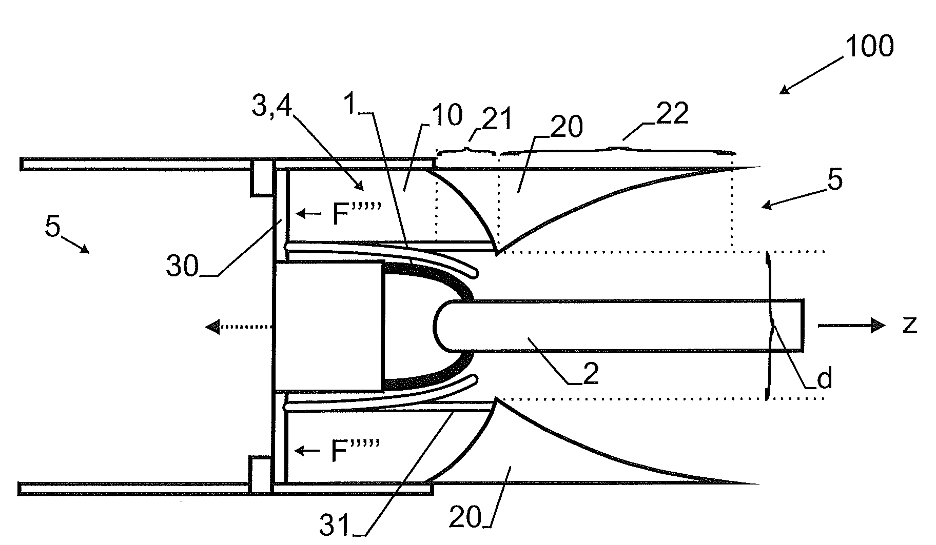
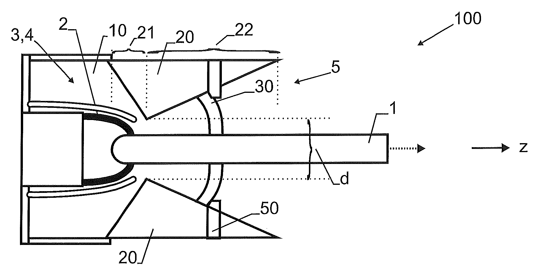
[0039] Figure 1a A cross-section through the first embodiment of the circuit breaker 100 is shown in the closed position. The circuit breaker 100 comprises a first arcing contact 1 and a second arcing contact 2 arranged coaxially (about the axis of symmetry z) in a tulip-plug configuration. The first arcing contact 1 is in the first position, ie electrically connected to the second arcing contact 2 . The quenching fluid (e.g. process air) 10 is provided in the pressure chamber 4 (wherein its volume e.g. is 3 liters), the pressure chamber 4 and the arcing chamber 3 of the circuit breaker 100 match. The term "arcing chamber" relates to the volume of the circuit breaker in which an electric arc is formed between the first and second arcing contacts 1 , 2 during separation of the arcing contacts 1 , 2 . The arc extinguishing or pressure chambers 3 , 4 are delimited on one side by a sealing wall 30 providing fluid tightness. The sealing wall...


PUM


Abstract

An improved medium- or high-voltage circuit breaker (100) is disclosed which is capable of faster contact separation and arc extinguishing performances while the setup of the circuit breaker is simplified. This is achieved by means of an arc-extinguishing fluid (10) stored in a pressure chamber (4), which is at least in part made up by an arcing chamber (3) of the circuit breaker (100) where an electrical arc is extinguished. No tubings or other conduction means for pressurized fluids are necessary during current interruption. This speeds up contact separation and arc extinguishing. In a first, closed position of the circuit breaker (100) the pressure chamber (4) is delimited by a sealing wall (30) which is fixed to a movable first arcing contact (1). The sealing wall (30) acts as a valve and as a piston at the same time, because it opens the outflow of pressurized arc extinguishing fluid (10) and it concurrently actuates arcing contact separation. Proper design and dimensioning of the arcing chamber (4) enables the stored pressurized arc extinguishing fluid (10) to perform very fast contact separation within few ms as well as extinguishing a gaseous arc (11) on the same timescale.

Description

technical field [0001] The invention relates to circuit breakers for medium or high voltage circuits. Furthermore, the invention relates to a method for breaking an electrical circuit by means of such a circuit breaker and the use of such a circuit breaker in a medium or high voltage transmission or distribution network. Furthermore, the invention relates to a power transmission or distribution network comprising such a circuit breaker. Background technique [0002] Prior art circuit breakers may comprise a compressed fluid (ie gas and / or liquid) as an energy storage and a piston mechanism as an actuator. In these devices, stored drive energy is typically used for both mechanical actuation (eg, separation) of electrical contacts and pressure buildup in the arc extinguishing fluid. During contact actuation, the nominal contacts (i.e. medium or high voltage contacts used during normal (non-trip) operation) and / or the arcing contacts in the arcing chamber (i.e. Medium or hig...

Claims


Application Information

Patent Timeline
Patent Type & Authority Applications(China)
IPC IPC(8): H01H33/91
CPCH01H33/7015H01H33/08H01H33/32H01H33/7084H01H1/385
Inventor E.帕诺西斯M.布福尼M.布约切克B.加莱蒂
Owner ABB TECH AG
Learn More