printing screen
A screen and screen technology, used in printing, printing machines, rotary printing machines, etc., can solve problems such as uneven printing of forming masks, and achieve the effect of being conducive to collection and transmission, reducing obstruction, and ensuring longevity.
- Summary
- Abstract
- Description
- Claims
- Application Information
AI Technical Summary
Problems solved by technology
Method used
Image
Examples
Embodiment 1
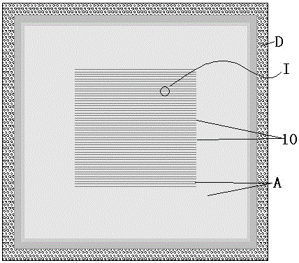
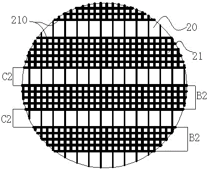
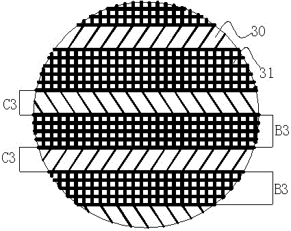
[0038] A printing screen, comprising a plane screen, is characterized in that the screen area of the plane screen is divided into a mask area A and a pattern area 10, such as figure 1 As shown; the mask area A is formed by a polygonal or circular array, in this embodiment, the mask area A can be formed by a rectangular array B2, B3 (such as figure 2 , image 3 shown) or regular polygon array B4 (such as Figure 4 shown) or circular array B5 (as Figure 5 shown) constitutes.
[0039] The pattern area is composed of a bridge array, and the bridge array forms a specific pattern in the pattern area 10; at the junction of the mask area A and the pattern area 10, the bridge unit of the pattern area 10 It is connected with the array unit structure of the mask area in a ratio of 1:(1-5).
[0040] In this embodiment, the bridging array can be composed of a rectangular array C2 (such as figure 2 shown) or the parallelogram C3 (as image 3 shown) or the combination array C4 of ...
Embodiment 2
[0045] A kind of printing screen plate, the basic structure of used plane screen is the same as embodiment 1, and used plane screen is as figure 1 As shown, it includes a grid area A and a non-grid area D, the grid area A is connected to the non-mesh area D, and the non-mesh area D is arranged on the periphery of the grid area A, the Grid area A is composed of two sets of grid lines perpendicular to each other, such as figure 2 , image 3 As shown, the middle area of the grid area A of the planar silk screen is provided with a pattern area 10, and the pattern area 10 is formed by the planar silk mesh bridging arrays B2, B3 (such as figure 2 , image 3 As shown), the flat screen has no braided nodes, its structure is integrally formed, and the surface is smooth, which means that the flat screen wires are coherent without braiding. It is composed of interlaced screen wires. In this embodiment, the mesh of the plane screen is 330 mesh, the wire diameter is 20um, and the th...
Embodiment 3
[0047] A printing screen, the basic structure of the plane screen used is the same as that of Embodiment 2, and the transformed part is as follows: the mesh number of the mesh is 400 mesh, the wire diameter of the mesh is 25um, and the thickness of the screen cloth is 20um.
[0048] On this basis, the planar screen has the following structural changes: the diameter of the remaining screen wires in the graphic area where the grid lines are missing has the following rules: grid area A line diameter r1>graphic area 10 constitutes a bridge array Bridging both ends line diameter r4>graphic area 10 constitutes the bridging middle line diameter r5 of bridge array; The described pattern area A constitutes the described bridging line diameter of described bridge array also can be following rule: figure area 10 The bridging line diameters are uniform in size, and there is a grid area A line diameter r1 ≥ pattern area 10 forming the bridging line diameter r6 of the bridging array. The ma...
PUM
 Abstract
Description
Claims
Application Information
 - Generate Ideas
- Intellectual Property
- Life Sciences
- Materials
- Tech Scout
- Unparalleled Data Quality
- Higher Quality Content
- 60% Fewer Hallucinations
Browse by: Latest US Patents, China's latest patents, Technical Efficacy Thesaurus, Application Domain, Technology Topic, Popular Technical Reports.
© 2025 PatSnap. All rights reserved.Legal|Privacy policy|Modern Slavery Act Transparency Statement|Sitemap|About US| Contact US: help@patsnap.com


