
Radar pulse compression filter optimization design method applied to random signal waveforms

A technology of signal waveform and radar pulse, applied in the field of optimal design of radar pulse compression filter

Active Publication Date: 2013-10-09
湖南鼎方电子科技有限公司
View PDF0 Cites 23 Cited by
  • Summary
  • Abstract
  • Description
  • Claims
  • Application Information

AI Technical Summary

Problems solved by technology

[0005] The purpose of the present invention is to overcome the deficiencies in the existing pulse compression filter design technology, provide a unified framework for radar pulse compression filter design for different forms of radar signal transmission waveforms, and focus on solving problems with main lobe width, processing gain loss and side lobe electrical Pulse Compression Filter Optimization Problem Under Equal Multiple Constraints

Method used


Image

  • Radar pulse compression filter optimization design method applied to random signal waveforms
  • Radar pulse compression filter optimization design method applied to random signal waveforms
  • Radar pulse compression filter optimization design method applied to random signal waveforms

Examples


Embodiment 1

[0086] Implementation example 1. Optimal design of pulse compression filter for phase-encoded signal

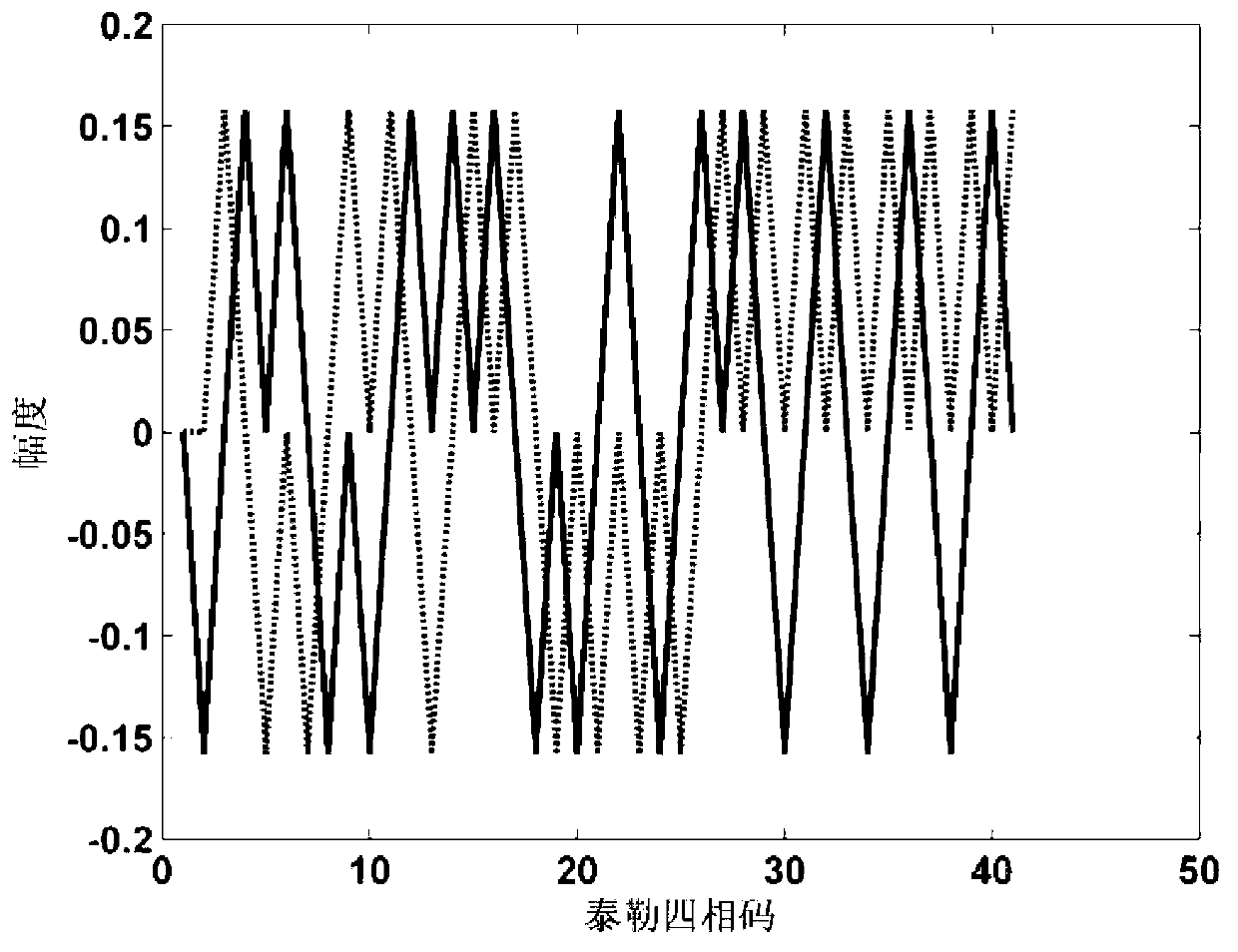
[0087] With 40 Taylor four-phase codes as the radar transmission signal, adopt the method of the present invention to optimize the design of the sidelobe suppression filter of the signal, the specific simulation parameters are as follows: signal sub-pulse width T=0.6us, signal sampling rate fs=1 / T, the Taylor quadrature code is obtained based on the optimized bi-phase code conversion, and the optimized bi-phase code is [0 1 0 1 1 0 1 0 0 1 0 1 1 1 0 0 00 1 1 1 0 1 1 1 1 0 0 0 1 0 0 0 1 0 0 0 1 0 0], the real and imaginary parts of the baseband complex signal of the normalized signal are as follows figure 2 As shown, the solid line and dashed line in the figure represent the real part and imaginary part of the baseband signal, respectively.

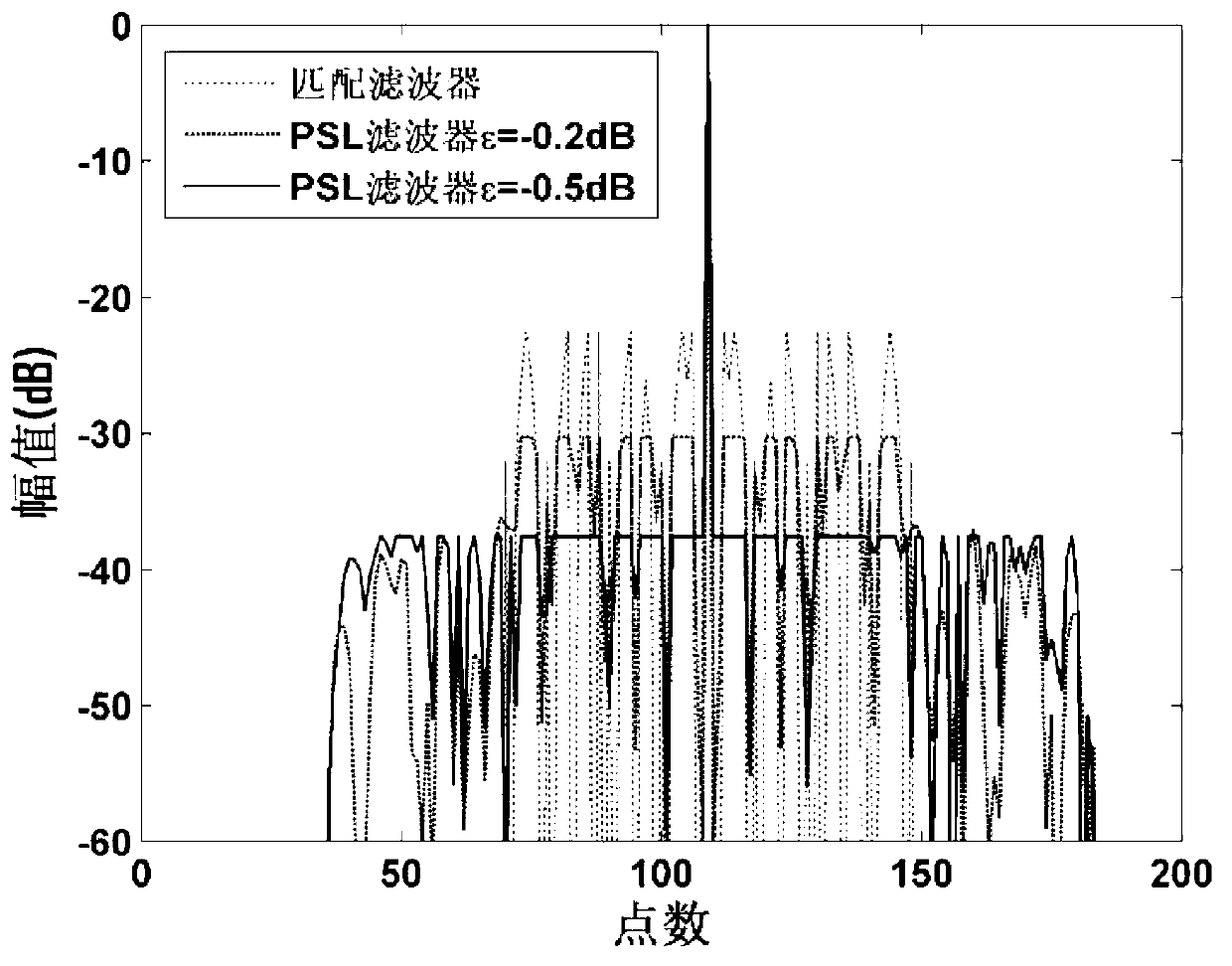
[0088] Set the length of the pulse compression filter to 109, and the width of the main lobe to 1 sampling point, and investigate the...

Embodiment 2

[0091] Implementation example 2. Optimal design of linear frequency modulation signal pulse compression filter

[0092] The invented method is used to design the low sidelobe filter for the chirp signal, and the simulation parameters are as follows: signal bandwidth B=2MHz, time width T=50us, sampling rate fs=4MHz. The real and imaginary parts of the baseband complex signal of the normalized signal are as Figure 9 As shown, the solid line and dashed line in the figure represent the real part and imaginary part of the baseband signal, respectively.

[0093] For the pulse compression processing of chirp signals, the length of the filter is usually selected to be consistent with the length of the signal. In the simulation, the length of the pulse compression filter is set to be consistent with the length of the signal. The length of the filter is determined by the sampling rate and the signal duration to be 200. The width of the main lobe is 5 sampling points, and the design ef...


PUM


Abstract

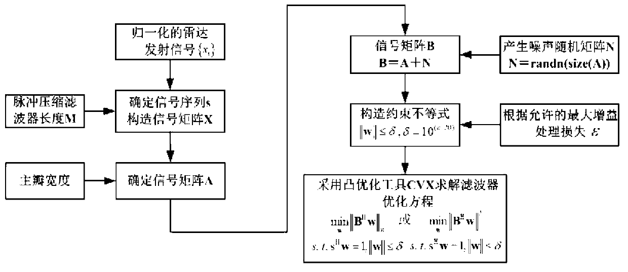
The invention discloses a radar pulse compression filter optimization design method applied to random signal waveforms. The method mainly solves the problem of pulse compression filter optimization design under constraint conditions of a main lobe width, processing gain loss and a sidelobe level. The radar pulse compression filter optimization design method includes the steps that firstly, new signal vectors are designed for radar transmitting signal waveforms and the filter length, and a signal matrix is established on the basis of the new signal vectors and is adjusted according to the pulse compression main lobe width at the same time; secondly, the allowable maximum processing gain loss is processed combined with pulse compression to form a constrained optimization equation; finally, the optimal filter coefficient under the constraint conditions is solved and obtained through a convex optimization tool. The optimal sidelobe level can be obtained under the conditions of the given pulse compression filter length, the main lobe width and the processing gain loss, meanwhile the method has the advantage of being irrelevant to signal modes, and the method is applied to signal pulse compression filter design of linear frequency modulation, phase encoding, frequency encoding and the like.

Description

technical field [0001] The invention belongs to the field of radar signal processing, and specifically relates to a method for optimizing the design of a radar pulse compression filter. Aiming at any known waveform of a radar transmission signal, the length of the pulse compression filter, the width of the main lobe and the loss of processing gain are given. Under these conditions, a pulse compression filter with optimal sidelobe level performance is designed to achieve optimal processing of radar echo signals. Background technique [0002] In order to meet the dual requirements of improving the detection distance and distance resolution, the radar system generally uses a large time-width-bandwidth product signal. Pulse compression processing compresses the transmitted wide pulse signal into a narrow pulse signal. It can transmit wide pulses to improve the average power and The detection capability of the radar, while maintaining the range resolution of narrow pulses. The p...

Claims


Application Information

Patent Timeline
Patent Type & Authority Applications(China)
IPC IPC(8): G01S7/292
Inventor 何学辉苏涛
Owner 湖南鼎方电子科技有限公司
Learn More