Steel PDC drilling bit with erosion-proof tooth cavities

An anti-erosion and tooth cavity technology, which is applied in the direction of drill bits, drilling equipment, earthwork drilling and mining, etc., can solve the problems of increasing the drilling resistance of the drill bit, wearing the back of the drill bit blade, limiting the mechanical penetration rate of the drill bit, etc., so as to improve rock breaking efficiency, avoiding drill failure, and reducing interference

Active Publication Date: 2013-10-09
KINGDREAM PLC CO +1
View PDF8 Cites 4 Cited by
  • Summary
  • Abstract
  • Description
  • Claims
  • Application Information

AI Technical Summary

Problems solved by technology

When the drill bit drills at high speed, because the drill bit moves downward in a spiral, after the cutting tooth breaks the rock, the nose and shoulder of the blade blade of the drill bit produce more cuttings, and there will be a certain retention behind the tooth, thus forming The accumulation of cuttings behind the blade will not only limit the cutting depth of the drill bit cutting into the formation, wear the back of the blade of the drill bit, but also increase the drilling resistance of the drill bit, thus limiting the further increase of the drilling speed of the drill bit , reduce the service life of the drill bit

Method used


Image

  • Steel PDC drilling bit with erosion-proof tooth cavities
  • Steel PDC drilling bit with erosion-proof tooth cavities
  • Steel PDC drilling bit with erosion-proof tooth cavities

Examples


Embodiment Construction

[0027] The present invention will be further described below in conjunction with the accompanying drawings.

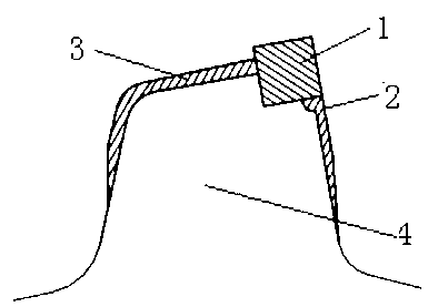
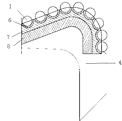
[0028] The first example is figure 1 , 2 , 3, including the drill bit body 10 and the curved blade 4 that is arranged on the periphery of the drill body and the end surface protruding outward at intervals, between the blades is a chip removal groove, and a nozzle 5 is arranged in the chip removal groove, and the front of the blade blade A tooth cavity is set up above, and the tooth cavity is a large semi-circular arc hole, and a cavity groove is provided along the edge of the tooth cavity at the front end of the tooth cavity. The depth is 3mm, the radial depth is 4mm, and the wear-resistant layer 6 is welded in the groove. The tooth cavities are arranged at intervals along the outer contour of the blade front, and are distributed in the inner cone, nose, shoulder and gauge section of the blade, and cylindrical composite sheet cutting teeth 1 are installed in the toot...


PUM


Abstract

The invention relates to a steel PDC drilling bit with erosion-proof tooth cavities which is used in the field of petroleum and geological drilling. The steel PDC drilling bit with the erosion-proof teeth comprises a drilling bit body and a knife wing, wearing layers are welded on the front face and the back face of the knife wing, the tooth cavities are formed in the upper portion of the front face of the knife wing, and clad sheet cutting teeth are arranged in the tooth cavities. The steel PDC drilling bit with the erosion-proof tooth cavities is characterized in that cavity grooves are formed in the front ends of the tooth cavities along the edges of the tooth cavities, and wearing layers are welded on the cavity grooves. According to the steel PDC drilling bit with the erosion-proof tooth cavities, the erosion-proof capacity of the front portions of the tooth cavities is enhanced, and thus the service life of the steel PDC drilling bit is prolonged. Further, more welding material is coated on certain parts around the tooth cavities, the thickness of the wearing layers is decreased gradually, the wearing layers around the tooth cavities are distributed reasonably, less welding material is used, and the machining cost of the drilling bit is decreased on the premise that the erosion-proof capacity of the tooth cavities is enhanced. Further, due to the fact that slopes which incline inwards are arranged on the back of the nose part and the shoulder parts of the knife wing, the interference between the back side of rock debris and a well bottom face behind the knife wing is reduced effectively, the drilling resistance of the drilling bit is decreased, the rock breaking efficiency of the drilling bit is improved, and the mechanical drilling speed of the drilling bit is increased.

Description

technical field [0001] The invention relates to a tooth cavity anti-erosion steel body PDC drill bit used in the field of petroleum and geological drilling, and belongs to the technical field of petroleum geological drilling tools. technical background [0002] When the steel body PDC bit is used for a long time or the bottom hole mud has a heavy sand content, the tooth cavity near the nozzle is easy to be eroded. The occurrence of this situation is mainly due to the relatively large wall shear stress on the erosion site, but the protection capacity of this site is relatively insufficient. The welding thickness of the existing steel body PDC drill bit cutting tooth cavity is 1.5~2mm, which is often prone to early failure of the drill bit caused by erosion of the drill bit cavity. The requirements for steel body PDC drill bits in the oil field are long service life and multiple repairs. Therefore, it is necessary to ensure that the drill bit does not appear erosion when it ...

Claims


Application Information

Patent Timeline
Patent Type & Authority Applications(China)
IPC IPC(8): E21B10/43E21B10/54
Inventor 涂关富石志明徐红
Owner KINGDREAM PLC CO
Why Eureka
Try Eureka