Method for manufacturing memory alloy spacecraft unlocking drive element
A technology of driving components and memory alloys, which is applied to space navigation equipment, space navigation vehicles, aircraft, etc., can solve the problems of not meeting the requirements of large displacement, large thrust, small elongation, and large restoring force. The effect of batch consistency, stable recovery force and recovery strain performance, and convenient loading and unloading
- Summary
- Abstract
- Description
- Claims
- Application Information
AI Technical Summary
Problems solved by technology
Method used
Image

Examples
Embodiment 1
[0044] (1) The raw material prepared with Ti-49.2% (at) Ni binary composition is prepared by casting, forging and rolling into a Ф10㎜ bar, which is machined after heat treatment to make a diameter and length of Ф7.78 0 -0.036 ㎜×84.5±0.1㎜ component blank. Mf=23.8°C Ms=49.2°C As=81.15°C Af=104.5°C of the alloy element.
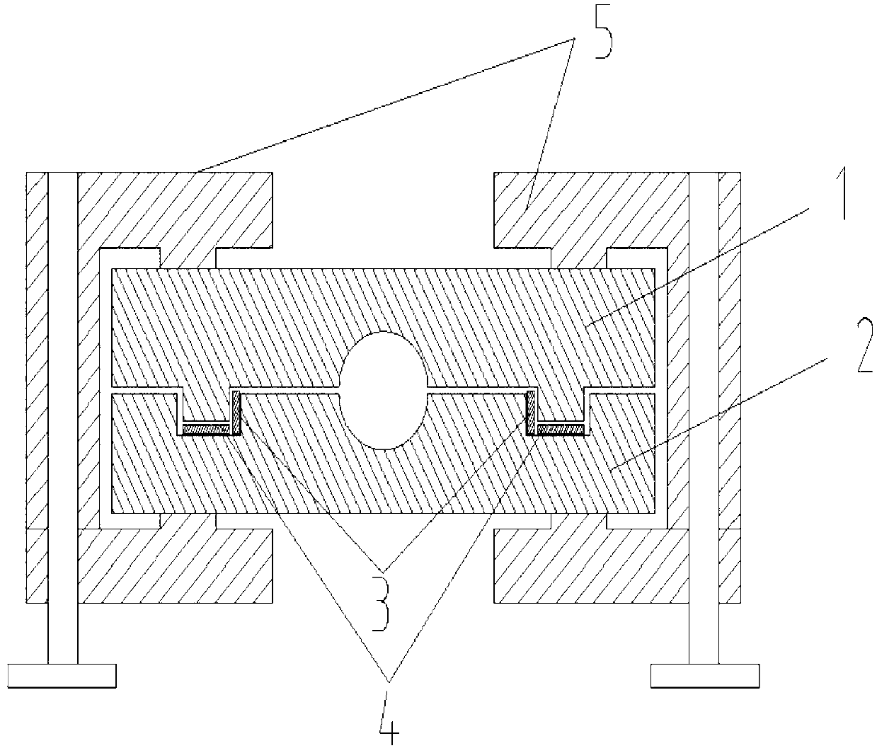
[0045] (2) Make attached figure 1For the mold shown, the height of the center hole of the mold is 76mm, and the diameter of the center hole is Ф8 0 -0.036 mm.
[0046] (3) Put the component blank with a diameter of Ф7.78 and the mold into the refrigerator to cool at -20°C for 40 minutes.
[0047] (4) Put the ice cubes made at minus 20°C in a plastic bag between the two indenters of the press that is in contact with the component blank, and cool the indenters for 10 minutes.
[0048] (5) attached figure 1 Quickly assemble the mold, put the element blank into the mold hole, quickly remove the cooling bag, and put the mold filled with the drive element blank...
Embodiment 2
[0053] Raw materials prepared with Ti-49.8% (at) Ni% binary components, Ф10㎜ bars prepared by casting, forging and rolling, and machined after heat treatment to make diameter and length Ф7.78 0 -0.036 ㎜×42.25±0.1㎜ two component blanks. Mf=20.2°C, Ms=52.3°C, As=63.8°C, Af=92.9°C of the alloy element.
[0054] (1) Make attached figure 1 For the mold shown, the height of the center hole of the mold is 76mm, and the diameter of the center hole is Ф8 0 -0.036 mm.
[0055] (2) Repeat steps (2)-(5) of Example 1, and put the two blanks into the center hole of the mold at the same time.
[0056] (3) Press the billet to 7.2% at a rate of 1.0mm / min and unload it. Take out the mold and drive components, loosen the clamp screws, and take out the drive components.
[0057] (4) The drive element specification is Ф8×39.95㎜. Recovery stressб r ﹦381MPa, elongation ΔL﹦1.91mm, recovery strain ε﹦4.51%.
[0058] (5) The combined length (or height) of the driving elements is 79.9mm, and th...
Embodiment 3
[0060] (1) Using Ti-47.2% (at) Ni-10% (at) Zr-2% (at) Cu quaternary components as raw materials, Ф10㎜ bars prepared by casting, forging, rolling, after heat treatment Machined to make diameter and length Ф7.78 0 -0.036 ㎜×28.33±0.1㎜ three component blanks. Mf=37.5°C Ms=61.3°C As=112.3°C Af=135.5°C of the alloy element.
[0061] (2) Make attached figure 1 For the mold shown, the height of the center hole of the mold is 76mm, and the diameter of the center hole is Ф8 0 -0.036 mm.
[0062] (3) Repeat steps (2)-(5) of Example 1, and put three blanks into the center hole of the mold at the same time.
[0063] (4) Press the billet to 7.5% at a rate of 0.5 mm / min and then unload it. Take out the mold, loosen the clamp screw, and take out the drive element.
[0064] (5) The drive element specification is Ф8×26.65㎜. Recovery stressб r ﹦410MPa, elongation ΔL﹦1.22mm, recovery strain ε﹦4.63%.
[0065] (6) The combined length (or height) of the driving elements is 79.95mm, and th...
PUM
| Property | Measurement | Unit |
|---|---|---|
| length | aaaaa | aaaaa |
Abstract
Description
Claims
Application Information
 - R&D
- Intellectual Property
- Life Sciences
- Materials
- Tech Scout
- Unparalleled Data Quality
- Higher Quality Content
- 60% Fewer Hallucinations
Browse by: Latest US Patents, China's latest patents, Technical Efficacy Thesaurus, Application Domain, Technology Topic, Popular Technical Reports.
© 2025 PatSnap. All rights reserved.Legal|Privacy policy|Modern Slavery Act Transparency Statement|Sitemap|About US| Contact US: help@patsnap.com