
Miniaturized, low-profile and three-ring-shaped RFID tag antenna capable of working under ultra high frequency (UHF) band

A technology of RFID tags and tag antennas, applied in miniaturized, omnidirectional electronic tags, and low-profile fields, to achieve good performance and reduced overall volume

Inactive Publication Date: 2013-10-02
BEIJING UNIV OF POSTS & TELECOMM
View PDF3 Cites 9 Cited by
  • Summary
  • Abstract
  • Description
  • Claims
  • Application Information

AI Technical Summary

Problems solved by technology

The invention provides a method to solve the problem of further miniaturization of the tag antenna, and is especially suitable for application in fields requiring tag antenna miniaturization, omnidirectionality and special requirements for tag shape

Method used


Image

  • Miniaturized, low-profile and three-ring-shaped RFID tag antenna capable of working under ultra high frequency (UHF) band
  • Miniaturized, low-profile and three-ring-shaped RFID tag antenna capable of working under ultra high frequency (UHF) band
  • Miniaturized, low-profile and three-ring-shaped RFID tag antenna capable of working under ultra high frequency (UHF) band

Examples


Embodiment Construction

[0022] The technical solutions of the present invention will be further described below in conjunction with the accompanying drawings and specific embodiments.

[0023] It should be understood that the specific embodiments described here are only used to explain the present invention, not to limit the present invention.

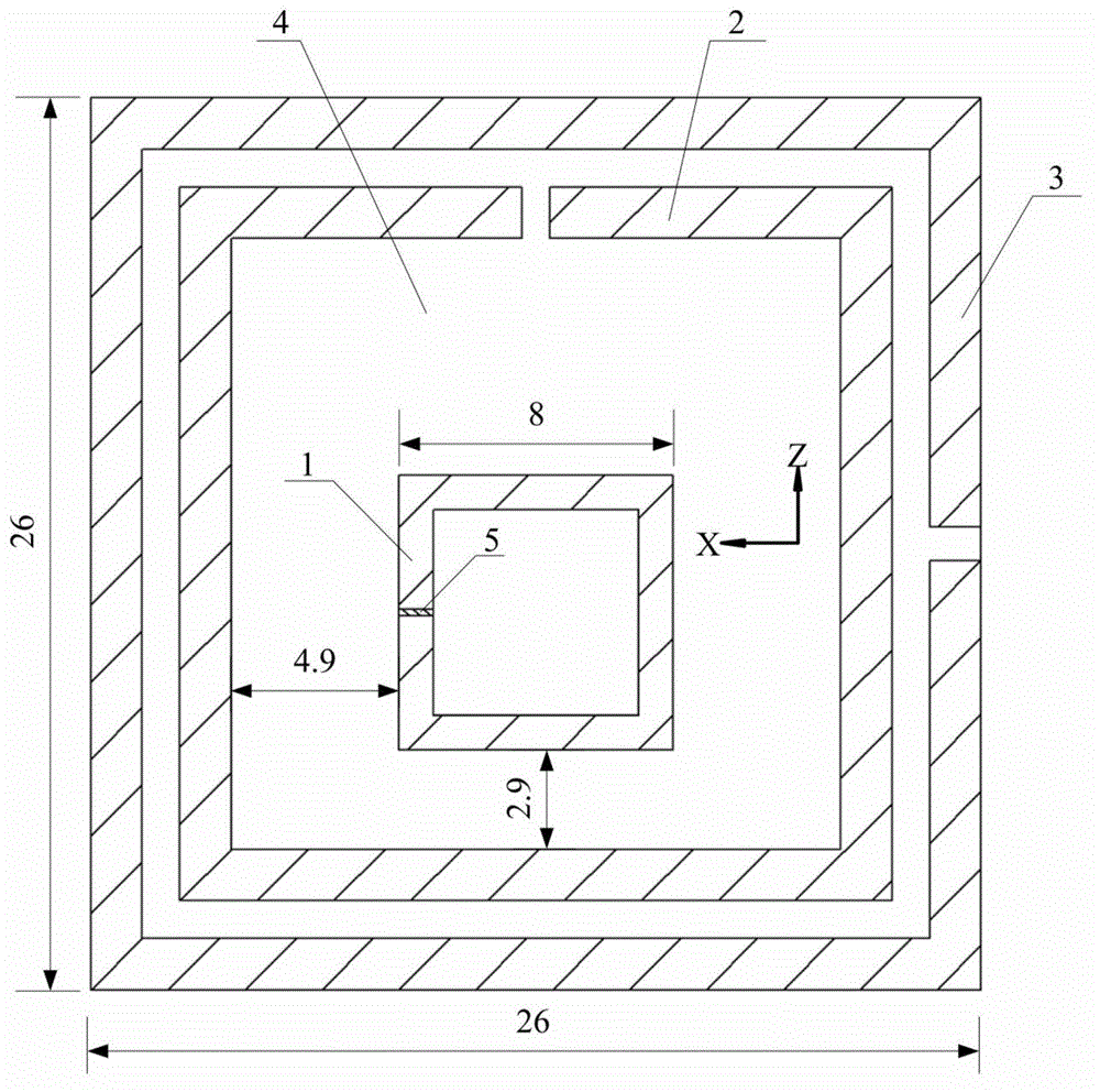
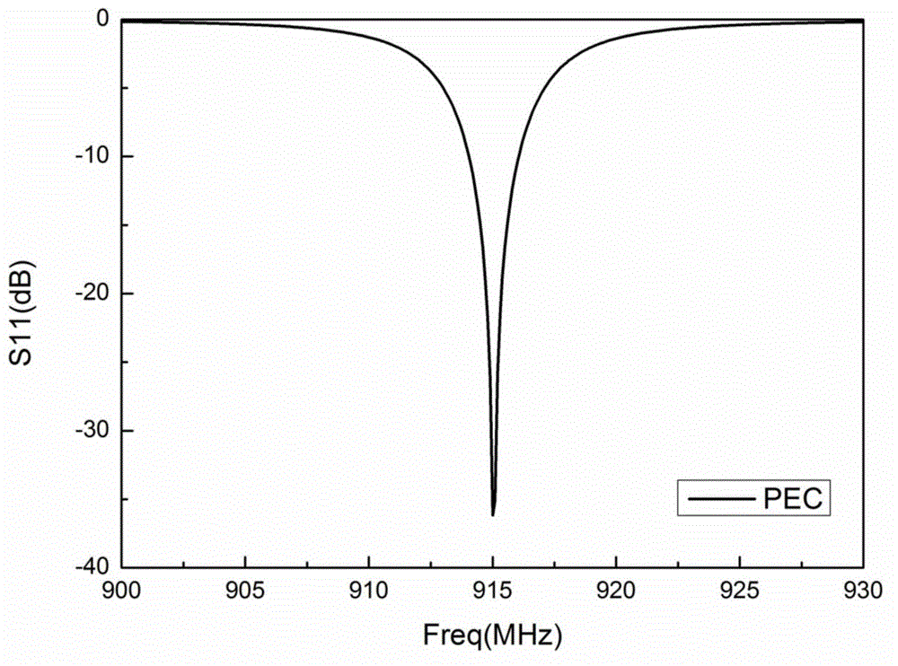
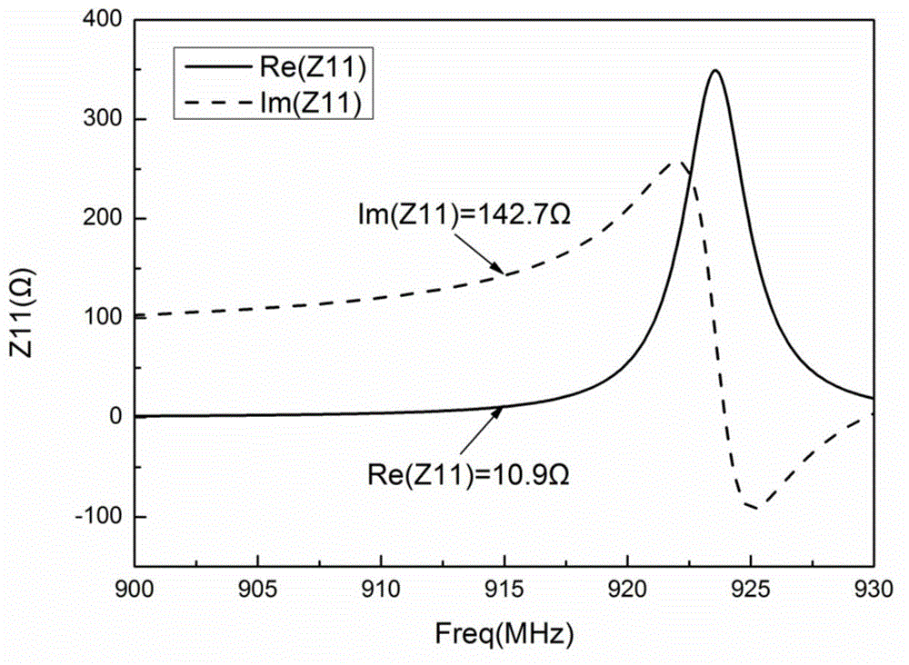
[0024] figure 1 It is a structural schematic diagram of a preferred embodiment of a miniaturized, low-profile, three-ring RFID tag antenna working in the UHF frequency band of the present invention. This embodiment includes a rectangular substrate 4 (ε r =4.4,μ r =1), RFID tag chip 5 (Monza4 chip is used in this embodiment, the impedance is 11-j143Ω when the working frequency is 915MHz), inner ring 1, smaller outer ring 2 and larger outer ring 3. By adjusting the dielectric constant and thickness of the substrate 4, the inner ring 1, the smaller outer ring 2, the larger outer ring 3 and the size of their openings, the input impedance and operating frequenc...


PUM


Abstract

The invention discloses a miniaturized, low-profile and three-ring-shaped RFID tag antenna capable of working under an ultra high frequency (UHF) band and belongs to radio frequency identification technical field. According to the tag antenna, three conductor rings are machined on one surface of a substrate so as to form an antenna structure, wherein an inner ring is a closed conductor ring which is connected with a chip, outer rings are two opening conductor rings of which opening directions are separated by 90 degrees; the rings can be round, rectangular or in other shapes, while, the performance of the rings is just changed slightly. The tag antenna can be applied to the ultra high frequency band or a microwave band. Under 915MHz-center frequency, and with a Monza4 chip adopted, the size of the tag antenna of the invention is only 26*26*0.8mm<3>(0.08*0.08*0.002 lambda <3>). The tag antenna has the advantages of small size, low profile excellent omnidirectivity and the like. The tag antenna can be applied to other chips and working frequencies with simple adjustment required. The invention provides a method for further miniaturizing the tag antenna, and is especially suitable for fields with special requirements for the miniaturization, omnidirectivity and shape of the tag antenna.

Description

technical field [0001] The invention relates to a radio frequency identification electronic tag, especially a miniaturized, low-profile, omnidirectional electronic tag. Background technique [0002] Radio Frequency Identification (RFID) technology is a technology that conducts non-contact two-way data communication through radio frequency to identify targets. An RFID system usually consists of a reader and an electronic tag. The electronic tag is composed of a tag chip and a tag antenna. It exchanges data with the reader through electromagnetic waves, and has functions such as intelligent reading and writing and encrypted communication. The tag antenna is a vital part of the RFID system. The RFID system transmits and receives electromagnetic waves through the tag antenna, thereby realizing the identification of the electronic tag by the reader. [0003] RFID systems mainly work in low frequency, high frequency, ultra high frequency and microwave frequency bands. Among the...

Claims


Application Information

Patent Timeline
IPC IPC(8): H01Q7/00
Inventor 李莉王霖川
Owner BEIJING UNIV OF POSTS & TELECOMM
Learn More