
Tandem built-in valve and liquid level control valve

A series, valve plate technology, applied in the direction of lift valve, valve details, valve device, etc., can solve the problem of wasting water resources, save time, overcome lax and tight closing effects

Inactive Publication Date: 2013-10-02
深圳市金润建设工程有限公司
View PDF5 Cites 2 Cited by
  • Summary
  • Abstract
  • Description
  • Claims
  • Application Information

AI Technical Summary

Problems solved by technology

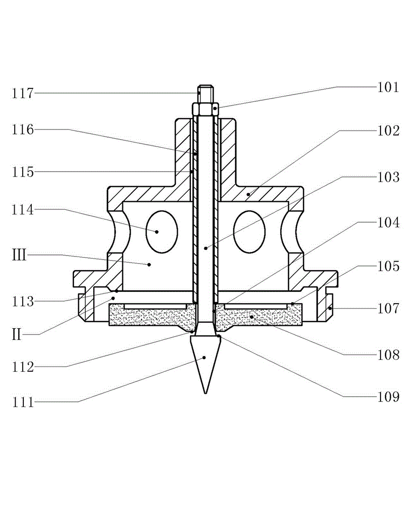
[0004] The purpose of this invention is to overcome the shortcomings of existing water level control valves and solve the problem of automatic water replenishment for solar water heaters, and design a serial built-in valve and liquid level control that is easy to install and use, reliable in operation, tight in closure and water-tight, and long in service life. valve, save people time and avoid wasting water resources

Method used


Image

  • Tandem built-in valve and liquid level control valve
  • Tandem built-in valve and liquid level control valve
  • Tandem built-in valve and liquid level control valve

Examples


Embodiment 1

[0016] Embodiment 1 Attached figure 1 In the shown embodiment, the tandem built-in valve is mainly composed of a valve seat (102), a main valve plate (108) and a pressure relief valve core (111). The front end of the built-in valve faces downward, and the pressure relief valve core (111) passes through The connecting rod (103) connects the main valve plate (108) and the valve seat (102) in coaxial series from bottom to top, wherein the main valve plate (108) is a disc structure, and the center of the main valve plate (108) has A circular through hole; the valve seat (102) is a dome structure, and the axial center of the rear end of the valve seat (102) has a slideway (115) for the connecting rod; the pressure relief valve core (111) is a cone structure, and the connecting rod (103) is connected from the center of the rear end of the cone; the connecting rod (103) on the pressure relief valve core (111) passes through the circular through hole in the center of the main valve pl...

Embodiment 2

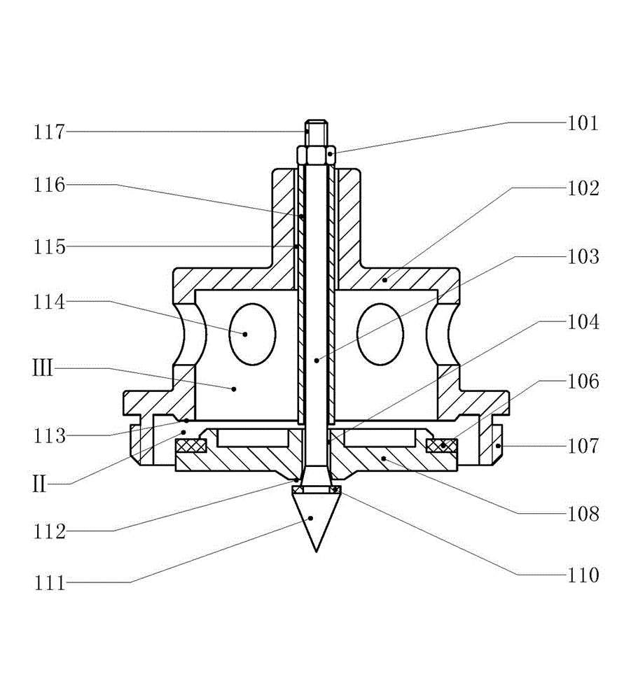
[0017] Embodiment 2 Attached figure 2 In the shown embodiment, on the basis of the first embodiment, the sealing surface a (105) on the main valve plate (108) is replaced by the rubber gasket a (106), and on the rear end surface of the main valve plate (108) There is an annular bayonet, and the rubber pad a (106) is fixed by the annular bayonet; there are snap rings and rubber pad b (110) on the annular end face of the rear end of the pressure relief valve core (111), and the rubber pad b (110) is fixed by The snap ring is fixed, and the rubber pad b (110) is matched with the sealing surface d (112) at the front end of the main valve plate (108). Other features of this embodiment are the same as those of the first embodiment and will not be repeated here.

Embodiment 3

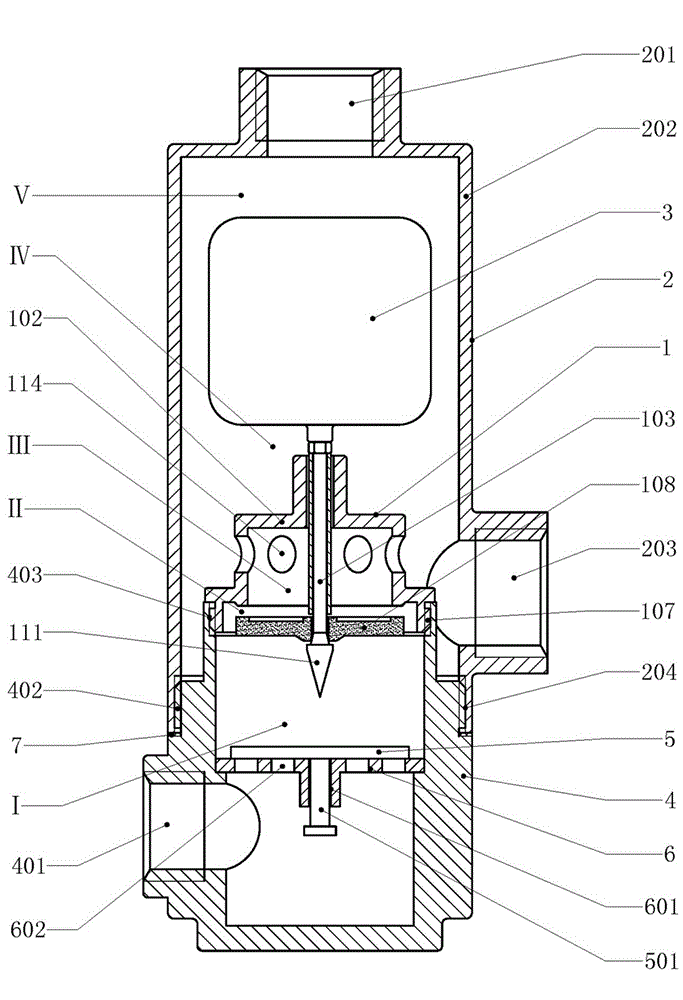
[0018] Example 3 Attached image 3In the shown embodiment, the liquid level control valve is mainly composed of a built-in valve (1), an upper valve body (2), a float (3) and a lower valve body (4), wherein the built-in valve (1) is a series structure, The built-in valve (1) consists of a valve seat (102), a main valve plate (108) and a pressure relief valve core (111). The main valve plate (108) is a disc structure, and the center of the main valve plate (108) has a The circular through hole in the center of the main valve plate (108) constitutes the pressure relief channel (104), and the peripheral annular end surface of the front end of the pressure relief channel (104) forms the sealing surface d (112). The outer ring-shaped end surface of the valve end constitutes the sealing surface a (105); the valve seat (102) is a dome structure, and there is a slideway (115) of the connecting rod in the center of the rear end of the valve seat (102), and the valve seat (102) There i...


PUM


Abstract

The invention discloses a tandem built-in valve and relates to an automatic water replenishing valve. The tandem built-in valve mainly comprises a valve seat, a main valve plate and a pressure relief spool. The main valve plate is a disc body structure. A round through hole is formed in the center of the main valve plate. The valve seat is a circular cap structure. A sliding way for a connecting rod is arranged in the axial center of the rear end of the valve seat. The pressure relief spool is a cylindrical or conical structure. The connecting rod is connected rearwards from the center of the bottom end of the conical structure. After the connecting rod penetrates through the circular through hole in the center of the main valve plate, the connecting rod penetrates out from the sliding way in the center of the rear end of the valve seat. The circular through hole in the center of the main valve plate forms a pressure relief passage. A water flow through hole is formed on a wall body behind the sealing surface b of the valve seat. An assembling interface a is arranged at the front end of the valve seat and is connected to the lower valve body of a liquid level control valve. The tandem built-in valve is suitable for water tanks of solar water heaters and centralized heat supply systems, water towers of industrial and mining enterprises, firefighting water ponds and boiler water replenishing tanks.

Description

technical field [0001] The invention relates to an automatic liquid level control device, in particular to an automatic water replenishing valve. Background technique [0002] People need water storage equipment in life and production, including thermal insulation water tanks for solar water heaters, water tanks for central heating systems, water towers for industrial and mining enterprises, fire pools and boiler water tanks, etc. Automatic liquid level control devices are used in these equipment Performing rehydration saves labor and prevents water wastage. When tap water is used to replenish water to the above-mentioned water storage equipment, it is convenient and economical to apply a water level control valve to replenish water. However, the existing water level control valve is controlled by a float valve, and the valve plate or valve core is closed against the water flow or water pressure direction of the tap water, which is likely to cause the disadvantage of not b...

Claims


Application Information

Patent Timeline
Patent Type & Authority Applications(China)
IPC IPC(8): F16K1/00F16K27/02F16K31/22
Inventor 周昀煜
Owner 深圳市金润建设工程有限公司
Learn More