
Power supply system and current control method thereof

A technology of power supply system and current control, which is applied in the direction of electric light source, energy-saving control technology, lamp circuit layout, etc., and can solve the problems of reducing product competitiveness, increasing R&D costs and manufacturing costs, etc.

Inactive Publication Date: 2013-09-25
DELTA ELECTRONICS INC
View PDF9 Cites 3 Cited by
  • Summary
  • Abstract
  • Description
  • Claims
  • Application Information

AI Technical Summary

Problems solved by technology

In this way, for the same specification of equipment or component products, although only changing the size of the output current, it is necessary to apply for other safety models, which will greatly increase the initial research and development costs of the product and the manufacturing after mass production. Fees, as such, will reduce product visibility and corporate competitiveness

Method used


Image

  • Power supply system and current control method thereof
  • Power supply system and current control method thereof
  • Power supply system and current control method thereof

Examples


Embodiment Construction

[0061] Relevant technical content and detailed description of the present invention, cooperate drawing description as follows:

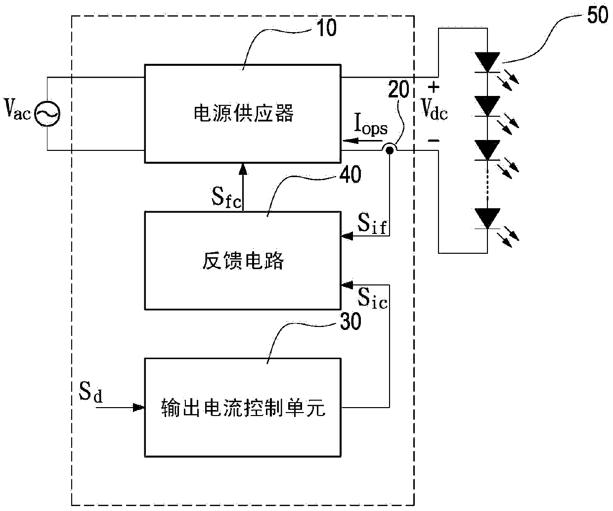
[0062] See figure 1 , is a circuit block diagram of a light-emitting diode (light-emitting diode, LED) driving power supply system of the present invention. Wherein, the LED driving power supply system shown in the first figure is only a diagram of a specific embodiment of the present invention, but the features of the present invention are not limited thereto, and are not intended to limit the present invention. Similar variants of the system should be included in the scope of the present invention. The LED driving power supply system is used to provide current control dimming operation for the LED lamp string 50 . The LED driving power supply system mainly includes a power supply 10 , a current detection unit 20 , an output current control unit 30 and a feedback circuit 40 .

[0063] The power supply 10 receives an external AC power Vac, and con...


PUM


Abstract

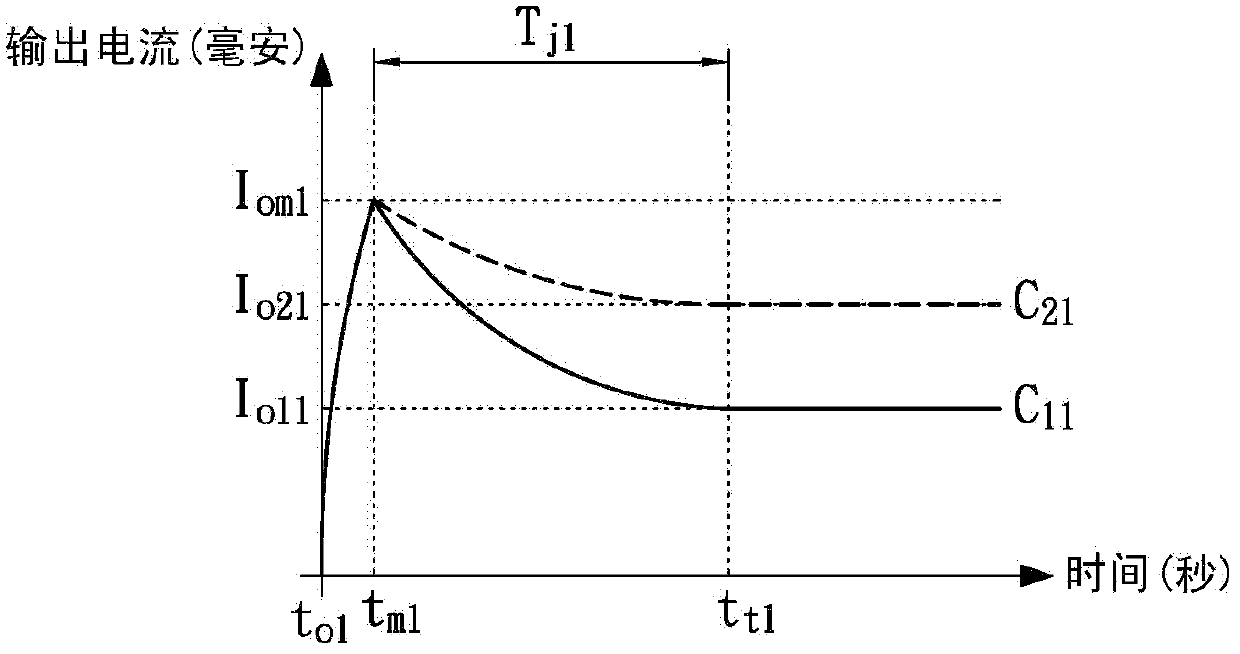
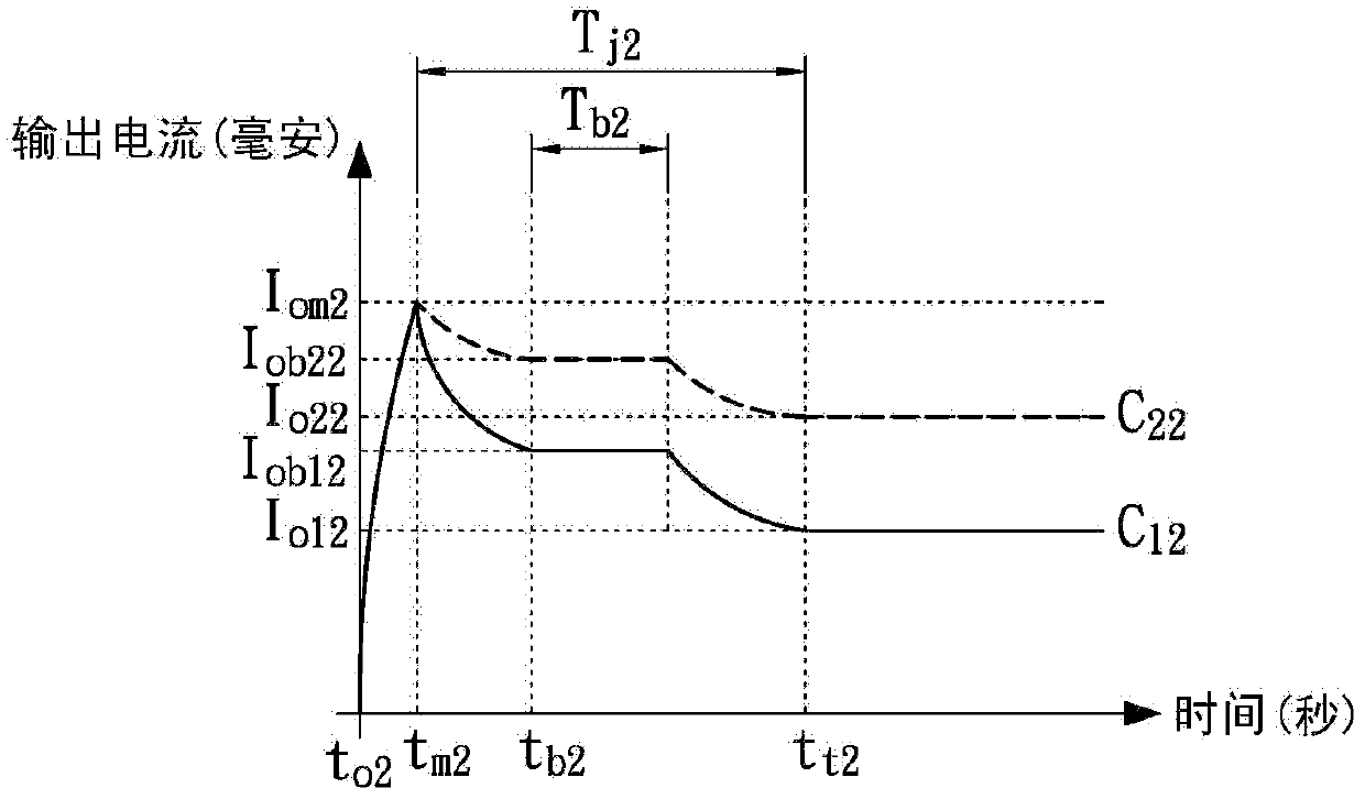
The invention discloses a power supply system and a current control method of the power supply system. The method comprises the following steps: when a power supply device is started, an output current generated by the power supply device is increased; then, when the output current is increased to reach a rated output current value, the output current begins to be decreased; finally, when the output current is decreased to reach a normal-state output current value, the output current is maintained to be the normal-state output current value.

Description

technical field [0001] The present invention relates to a power supply system and its current control method, and in particular to a current control method operating in a light emitting diode driving power supply system. Background technique [0002] Safety regulations are safety standard specifications. Safety regulations have clear statements and guidance on manufactured equipment and component products in order to provide safe and high-quality products to end users or operators. Its main purpose is to prevent and reduce hazards such as electric shock hazards, fire hazards, mechanical and thermal hazards, radiation hazards, chemical hazards, etc., and cause life and property damage to users and operators. Therefore, the manufactured equipment and components must pass the safety certification of various countries before they can be shipped. [0003] At present, most power supply (power supply) manufacturers generally use the International Electrotechnical Commission (IEC),...

Claims


Application Information

Patent Timeline
IPC IPC(8): H05B37/02
CPCY02B20/40
Inventor 吴享珍陈肇彬
Owner DELTA ELECTRONICS INC
Learn More