
Rubidium clock scanning and capturing auxiliary locking method

A rubidium clock and frequency synthesis technology, applied in the direction of electrical components, automatic power control, etc., can solve problems such as affecting the working state of the rubidium clock, unable to meet the use requirements of high-performance rubidium clock, and reducing the performance of the whole machine.

Active Publication Date: 2013-09-25
XIAN INSTITUE OF SPACE RADIO TECH
View PDF5 Cites 2 Cited by
  • Summary
  • Abstract
  • Description
  • Claims
  • Application Information

AI Technical Summary

Problems solved by technology

[0005] The existing expansion capture circuits are all based on the auxiliary locking of the servo circuit, and the biggest disadvantage is that auxiliary circuits such as hardware scanning oscillators are required
[0007] b. The servo-based auxiliary locking circuit finally superimposes the scanning level on the voltage control voltage terminal of the crystal oscillator. No matter how high the isolation degree is, it is impossible to completely achieve physical isolation. For high-precision rubidium clocks, the frequency stability index requirement is 3×10 -12 / 1s, crystal oscillator voltage control slope is 1×10 -7 / V or so, in theory, the voltage fluctuation control of the voltage control terminal of the crystal oscillator is required to be ≤0.03mV; if the noise is too large, the index performance of the whole machine will be reduced, and even the normal working state of the rubidium clock will be affected
[0008] It can be seen that the existing auxiliary locking method for rubidium clocks can no longer meet the needs of high-performance rubidium clocks, and a method that does not introduce additional interference noise sources is needed to replace

Method used


Image

  • Rubidium clock scanning and capturing auxiliary locking method
  • Rubidium clock scanning and capturing auxiliary locking method
  • Rubidium clock scanning and capturing auxiliary locking method

Examples


Embodiment Construction

[0021] The present invention will be further introduced below in conjunction with the drawings.

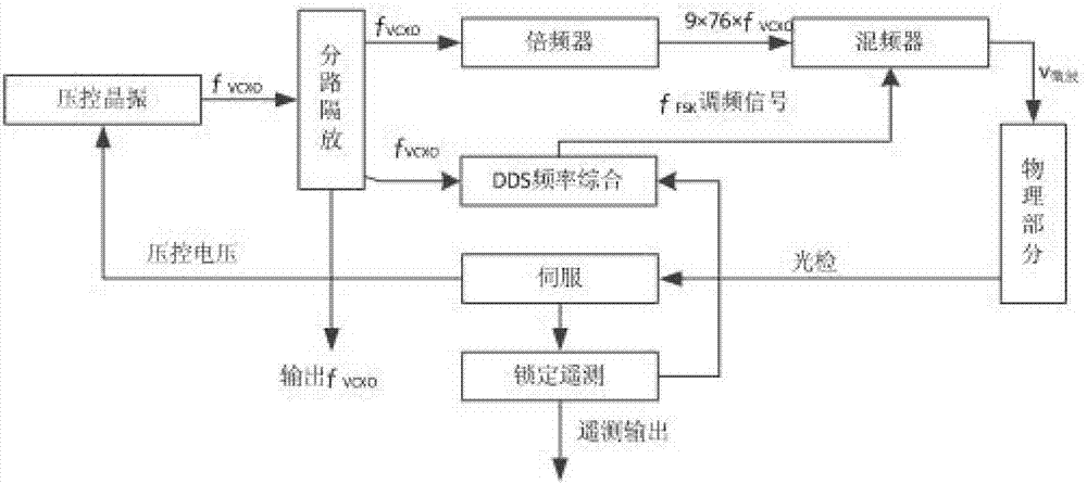
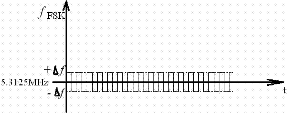
[0022] Such as figure 2 Shown is a block diagram of the rubidium clock of the present invention, including voltage-controlled crystal oscillator, shunt isolation amplifier circuit, DDS frequency synthesis circuit, frequency multiplier, mixer, physical part, servo circuit, and locking telemetry module. Signal f provided by voltage controlled crystal oscillator VCXO After splitting and amplifying the power by the shunt isolation amplifier circuit, it is divided into three channels, one is sent to the frequency multiplier, the other is sent to the DDS frequency synthesis circuit, and the output frequency of the third is f VCXO The output signal. DDS frequency synthesis circuit is used to generate frequency modulation signal f FSK , The resulting FM signal f FSK Input to the mixer. Signal f VCXO After passing through the frequency multiplier, it is input to the mixer for mixing, an...


PUM


Abstract

The invention discloses a rubidium clock scanning and capturing auxiliary locking method which utilizes an existing rubidium clock locking telemetering module and an existing DDS frequency synthetic circuit for judgment. When a rubidium clock is not locked, the DDS frequency synthetic circuit adjusts an output FSK signal frequency according to a certain cycle, frequency stepping and a frequency range. A microwave frequency can change along with the change of the FSK signal according to the correlation of the microwave frequency and the FSK signal frequency. When the microwave frequency enters into a pull-in range of a rubidium clock frequency locking loop, the rubidium clock can be in a locking state, and therefore the scanning and capturing auxiliary locking function is achieved. According to the rubidium clock scanning and capturing auxiliary locking method, hardware composition is reduced. For example, a low frequency oscillator is removed. In addition, any interfering noise does not exist, and meanwhile, the method has the advantage of being easy to debug.

Description

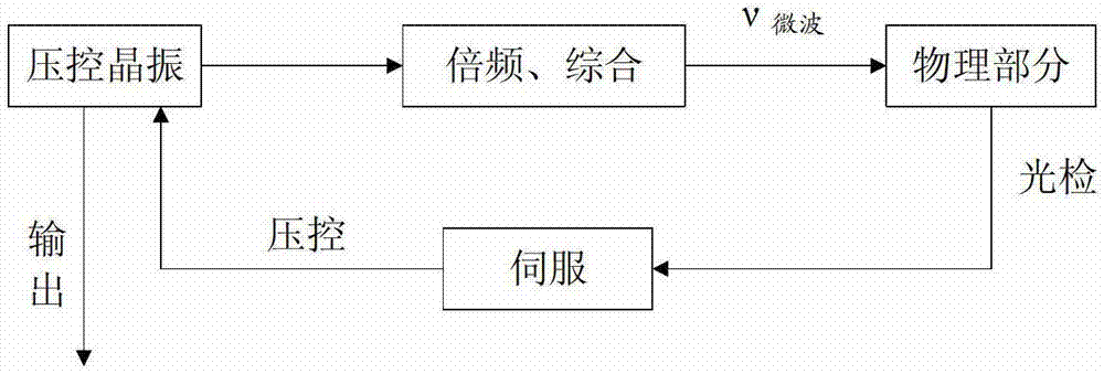
Technical field [0001] The invention relates to a rubidium clock scanning acquisition auxiliary locking method. Background technique [0002] Rubidium clock is the most widely used atomic clock. It has the advantages of small size, light weight, low power consumption, low price, high reliability, long life, and good short-term stability. It is convenient for miniaturization and mass production. The principle is like figure 1 Shown. [0003] The output signal of the voltage-controlled crystal oscillator generates a microwave signal ν through frequency multiplication and synthesis. microwave (Approximately 6834.6875MHz), sent to the physical part, namely the microwave cavity of the rubidium atomic resonator, which excites the atomic transition and generates a resonant signal, which changes the intensity of light passing through the 87Rb absorption bubble. It is detected and converted into electrical signals and sent to the servo circuit. After a series of processing, the servo circ...

Claims


Application Information

Patent Timeline
IPC IPC(8): H03L7/26
Inventor 屈勇晟刘昶贺玉玲杜二旺朱虹程冰胡家裕杨涛张荣彦秦玉浩
Owner XIAN INSTITUE OF SPACE RADIO TECH
Learn More