
Orthogonal double-cavity device for phase demodulation of FP cavity interferometer and demodulation method

A technology of phase demodulation and interferometer, which is applied in the direction of using optical devices to transmit sensing components, measuring devices, instruments, etc., can solve the problems of high laser center frequency and power stability, degradation of phase demodulation effect, and high cost of lasers. Achieve the effects of shielding metal and electromagnetic signal detection, simple and reliable optical path structure, and increasing feasibility

Inactive Publication Date: 2020-12-18
ANHUI UNIVERSITY
View PDF9 Cites 2 Cited by
  • Summary
  • Abstract
  • Description
  • Claims
  • Application Information

AI Technical Summary

Problems solved by technology

[0003] The current two-wavelength and three-wavelength FP cavity interferometer phase demodulation technology requires multiple wavelengths of lasers, which require high laser costs and require more laser center frequency and power stability; because the cavity length of the FP interferometer is affected by If the influence of the environment or the large dynamic detection physical quantity changes greatly, the phase demodulation effect will be degraded, distorted and other unstable phenomena

Method used


Image

  • Orthogonal double-cavity device for phase demodulation of FP cavity interferometer and demodulation method
  • Orthogonal double-cavity device for phase demodulation of FP cavity interferometer and demodulation method
  • Orthogonal double-cavity device for phase demodulation of FP cavity interferometer and demodulation method

Examples


Embodiment Construction

[0033] The technical solutions in the embodiments of the present invention will be clearly and completely described below. Obviously, the described embodiments are only some of the embodiments of the present invention, but not all of them. Based on the embodiments of the present invention, all other embodiments obtained by persons of ordinary skill in the art without creative efforts fall within the protection scope of the present invention.

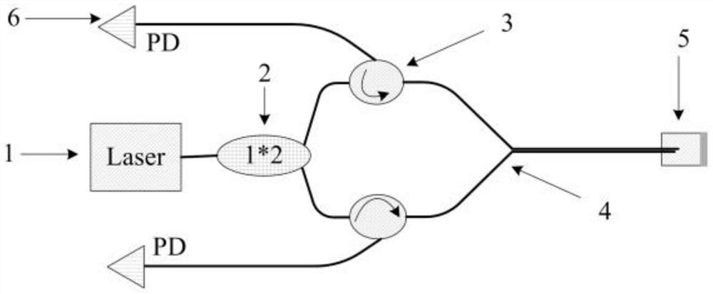
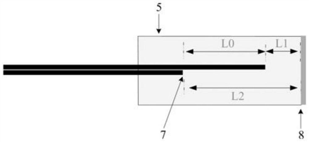
[0034] see Figure 1 to Figure 2 , the present embodiment discloses an orthogonal dual-cavity device for phase demodulation of FP cavity interferometers, including a laser 1, a fiber beam splitter 2, an optical circulator 3, several optical fibers 4, and an orthogonal dual FP cavity 5, A light detector 6, an optical fiber end face 7 and a reflective face 8.

[0035] The laser light emitted by the laser 1 is divided into two beams by the fiber beam splitter 2, and the beam is transmitted to the orthogonal double FP cavity 5 through the o...


PUM


Abstract

The invention discloses an orthogonal double-cavity device for phase demodulation of an FP cavity interferometer and a demodulation method. The device comprises a laser, an optical fiber beam splitter, an optical circulator, an optical fiber, an orthogonal double-FP cavity and a photoelectric detector; the laser, emitted by the laser, is split into two beams of light through the optical fiber beamsplitter, and the light beams are transmitted to the orthogonal double-FP cavity through the optical circulator; a light beam in the orthogonal double-FP cavity irradiates the reflecting surface, isreflected back to the optical fiber and interferes with reflected light of the end surface of the optical fiber, and interference light is transmitted to the photoelectric detector through the opticalcirculator and is converted into an electric signal; according to the orthogonal double-FP-cavity structure, parallel light beams emitted by an optical fiber end face irradiate the same film face, the optical fiber end face is staggered by a certain length in the axial direction, and the staggered length is matched with the wavelength of a laser, so that interference signals output by an orthogonal FP cavity are in an orthogonal state; finally, the change of the cavity length of the FP is analyzed and calculated by adopting a phase demodulation algorithm for the electric signal converted by the interference light beam.

Description

technical field [0001] The invention relates to a device and a demodulation method for optical sensing information demodulation, in particular to an orthogonal double-cavity device and a demodulation method for phase demodulation of an FP cavity interferometer. Background technique [0002] The development of society requires multi-level and high-depth acquisition of external information. Various sensors are the main way for us to obtain external information. Optical sensing, especially interferometric optical sensing, has attracted much attention due to its high sensitivity, anti-electromagnetic interference and wide applicability. In interferometric optical sensing, the difference of the interference arms often leads to polarization fading. The FP cavity interferometer has the advantages of anti-path interference and anti-polarization fading due to its same-path transmission and the existence of isotropic medium in the cavity; for For the phase fading problem of interfero...

Claims


Application Information

Patent Timeline
Patent Type & Authority Applications(China)
IPC IPC(8): G01D5/353
CPCG01D5/35312
Inventor 时金辉俞本立吴许强光东
Owner ANHUI UNIVERSITY
Learn More