Optimal Adjustment Circuit and Optimization Method of Switched Reluctance Motor Controller

A technology for switching reluctance motors and adjusting circuits, which is applied in the direction of single motor speed/torque control, sustainable manufacturing/processing, climate sustainability, etc., and can solve the problems of slow or too fast switching speed, power module breakdown, damage Controller and other issues, to achieve the effect of simple testing

Active Publication Date: 2015-08-05
淄博智科电气科技有限公司
View PDF1 Cites 0 Cited by
  • Summary
  • Abstract
  • Description
  • Claims
  • Application Information

AI Technical Summary

Problems solved by technology

Unlike general power frequency electrical appliances, the switched reluctance motor controller works in a fast switching state, and the current is very large. At this time, it will generate a large di / dt, a small inductance, and a large pulse high voltage. If the voltage exceeds the withstand voltage of the internal power semiconductor, it will cause breakdown of the power module, resulting in damage to the controller
[0004] The solution to avoid this problem is to reduce the inductance of the main circuit, the second is to add a protection circuit, and the third is to reduce the switching speed, but the three are contradictory to each other. First, due to the constraints of the controller space and materials, the inductance cannot be without The reduction of the limit always has the existence of inductance. Under certain circumstances, the high-voltage pulse caused by these stray inductances is enough to damage the power module. At the same time, the parameters added to the protection circuit are too large or too small, the switching speed is too slow or Too fast will cause the efficiency of the controller to be too low or damage the power module. Therefore, when designing the switched reluctance controller, it is necessary to fully consider all aspects of the controller, optimize the design, and find a reasonable balance parameter among the above factors. to achieve the best
[0005] The traditional test method requires high-power experimental equipment, and the cost of the equipment is very high; in the case of high current, if the parameter selection is unreasonable, the controller may be damaged even before the detection result, which affects the product. optimized design

Method used


Image

  • Optimal Adjustment Circuit and Optimization Method of Switched Reluctance Motor Controller

Examples


Embodiment 1

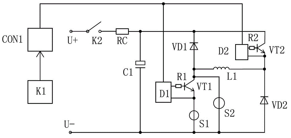
[0036] Such as figure 1 As shown, the optimized adjustment circuit of the switched reluctance motor controller includes an external DC power supply and a switched reluctance motor controller. The pulse trigger controller CON1 is set, and the output terminals of the pulse trigger controller CON1 are respectively connected to the first IGBT drive circuit D1 and The input end of the second IGBT drive circuit D2 and the output end of the first IGBT drive circuit D1 are connected to the gate of the first IGBT module VT1 through the first gate drive resistor R1, and the output end of the first IGBT drive circuit D1 is also connected to the first The emitter of the IGBT module VT1, the output terminal of the first IGBT drive circuit D1 and the common end of the emitter of the first IGBT module VT1 are provided with a current waveform measuring instrument S1, and the collector of the first IGBT module VT1 is provided with a voltage waveform measuring instrument S2, The external DC pow...

Embodiment 2

[0043] A method for optimizing a switched reluctance motor controller, comprising connecting the above optimization adjustment circuit to a switched reluctance motor controller, the method is as follows:

[0044] (1) Turn off the switch, close the main power switch, and the external DC power supply will charge the aluminum electrolytic capacitor through the main power switch and charging resistor until it reaches saturation, that is, when the voltage at both ends of the aluminum electrolytic capacitor is equal to U+ and U- of the external DC power supply , disconnect the main power switch; because the pulse time is very short, the current value is very large when the pulse is turned on, but the average value is small, and the test can be done only by the energy storage of the capacitor C1. Therefore, the test is relatively simple and safe. And no large power supply is needed.

[0045] (2) Adjust the measurement mode of the current waveform measuring instrument and the voltage ...


PUM


Abstract

The invention discloses an optimization and adjustment circuit and an optimization method of a switch reluctance motor controller, and belongs to the field of debugging devices of switch reluctance motor controllers. The optimization and adjustment circuit of the switch reluctance motor controller comprises a direct current power source and the switch reluctance motor controller. The optimization and adjustment circuit and the optimization method of the switch reluctance motor controller are characterized in that a pulse trigger controller is arranged, the output end of the pulse trigger controller is connected with an IGBT driving circuit, a current waveform measuring instrument and a voltage waveform measuring instrument are arranged, the current waveform and the voltage waveform on the current waveform measuring instrument and the voltage waveform measuring instrument are observed, the values of di / dt and dv / dt are judged, and therefore a main circuit structure and the sizes of gate drive resistors are adjusted till the best state is obtained. According to the optimization method of the switch reluctance motor controller, continual readjustment of parameters of the switch reluctance motor controller is achieved until the best structural state of the controller is achieved. The switch reluctance motor controller of the switch reluctance motor controller is simple in structure, convenient to use, wide in application range, and suitable for various controllers. The measuring devices are low in power and simple and easy to operate, and save energy.

Description

technical field [0001] The invention provides an optimization adjustment circuit and an optimization method of a switched reluctance motor controller, belonging to the field of debugging equipment for a switched reluctance motor controller. Background technique [0002] Chinese patent CN201120021234.6 discloses a switched reluctance motor controller, including an external power supply, characterized in that it also includes a microprocessor, a phase shift control circuit, a power amplifier circuit, a rectifier circuit and a motor switch, and the output The terminal is connected with the phase-shift control circuit and the power amplifier circuit, the power amplifier circuit is connected with the motor switch, the phase-shift control circuit is connected with the rectifier circuit, and the external power supply is connected with the motor switch through the rectifier circuit. It realizes the soft start of the DC bus voltage, avoids the impact of large current on the control s...

Claims


Application Information

Patent Timeline
Patent Type & Authority Patents(China)
IPC IPC(8): H02P6/08
CPCY02P80/10
Inventor 石光峰郭源生董义鹏李明贤
Owner 淄博智科电气科技有限公司
Why Eureka
Try Eureka