
Device and method for reducing noise

A technology for noise and switching elements is applied in the field of reducing the noise of a touch panel, and can solve the problems of lack of touch sensing methods, noise of touch modules, and inability to correctly identify finger interference noise.

Inactive Publication Date: 2013-09-25
ZEITEC SEMICON
View PDF4 Cites 0 Cited by
  • Summary
  • Abstract
  • Description
  • Claims
  • Application Information

AI Technical Summary

Problems solved by technology

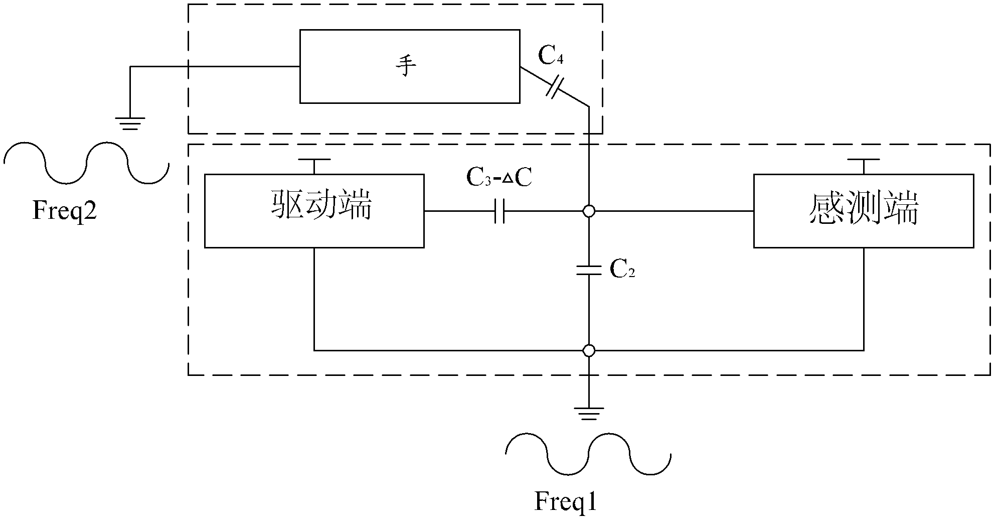
like Figure 1B As shown, Freq 1 and Freq 2 can be equivalent to noise Freq 3, and when the sensing terminal is operating, it can be equivalent to noise Freq 3 passing through the capacitor C 4 interference via capacitor C 3 -The signal path of the touch sensing signal of ΔC enters the sensing terminal together with the touch sensing signal, so it is impossible to correctly judge the touch change of the finger
In addition, in the design of the touch panel module, due to different designs, there may be enough interference noise affecting the sensing accuracy of the touch panel, and making the sensing end of the touch panel unable to correctly identify fingers.
[0003] In the prior art, the voltage range is usually increased at the driving end to increase the signal-to-noise ratio (SNR) of the above-mentioned touch sensing signal. However, due to the high-voltage driving, it is also necessary to increase the design of the entire finished system module. Its high / low voltage related protection measures will increase additional chip design and equipment costs
[0004] Therefore, since the prior art touch sensing method lacks an effective and economical mechanism to solve the noise problem of the touch module, it is extremely necessary to propose a novel touch sensing method capable of accurately sensing the touch on the touch panel. control address

Method used


Image

  • Device and method for reducing noise
  • Device and method for reducing noise
  • Device and method for reducing noise

Examples


Embodiment Construction

[0017] The detailed structure of the present invention and its connections are described in conjunction with the following drawings, so as to facilitate your review committee members to understand.

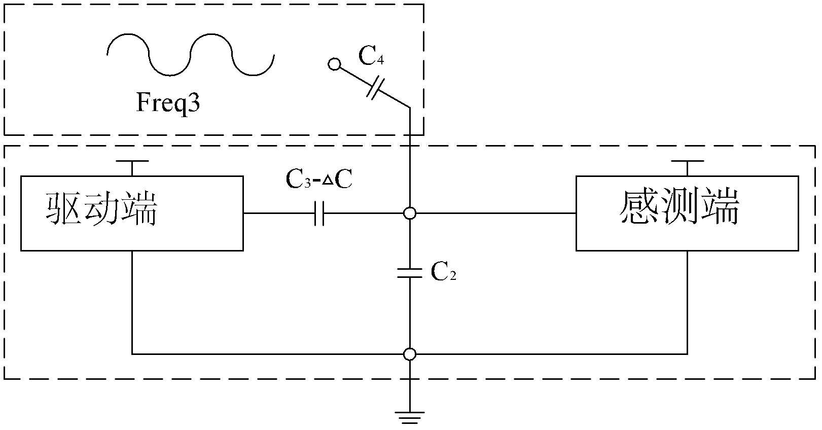
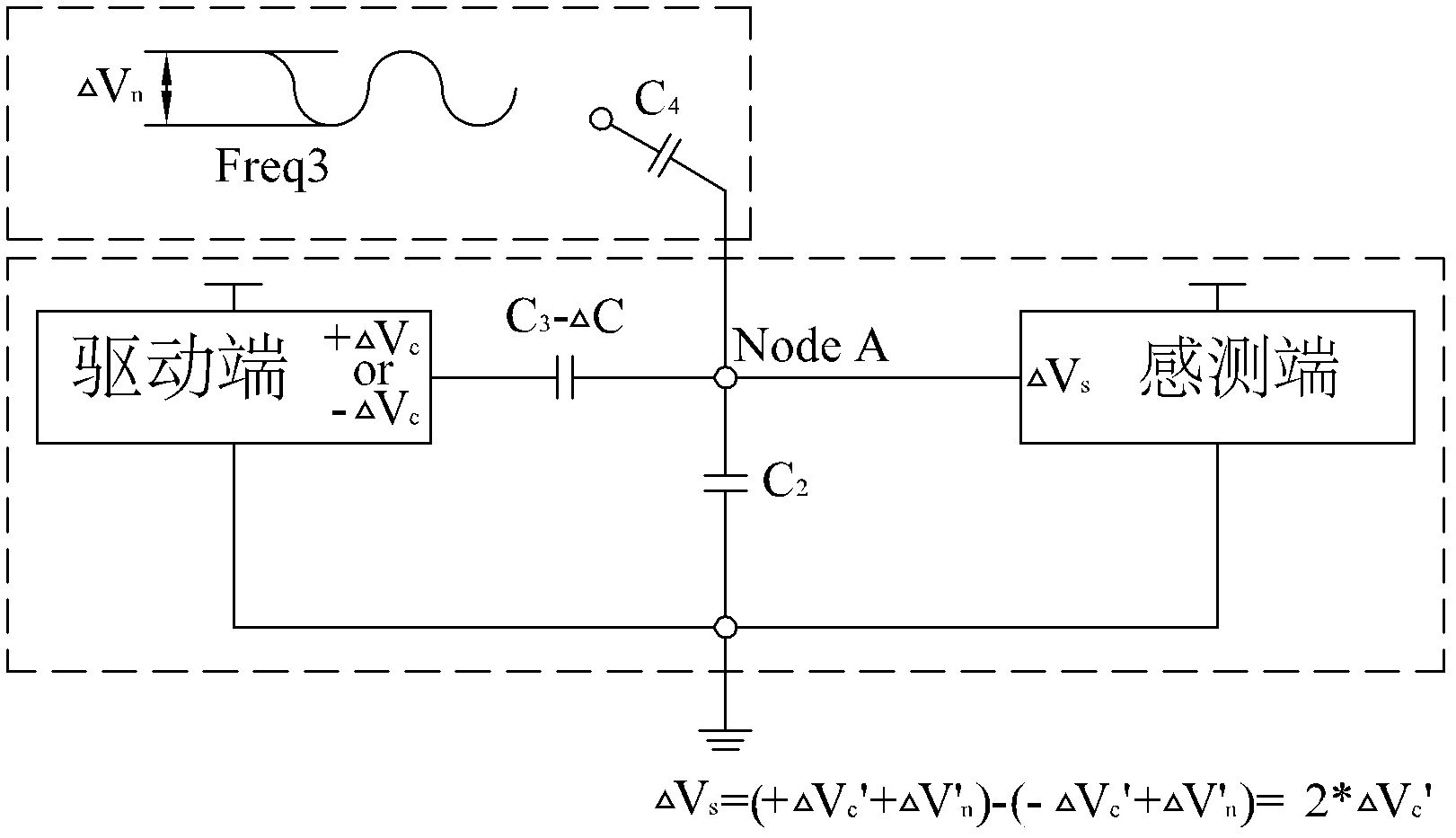
[0018] figure 2 A schematic diagram showing a part of the touch panel of the present invention. In this embodiment, positive pulses or negative pulses of the same phase are used to continuously trigger actions on the trajectory of the sensing end, and then the sensing end obtains an induction value as a basis for judging the finger. Therefore, if figure 2 As shown, the present invention subtracts the induction value obtained by a forward pulse and the sensing terminal from the induction value obtained by a reverse pulse and the sensing terminal, and at the same time, the capacitor C 4 The loaded noise Freq 3 will cancel each other due to the same phase, so that the inductance obtained on the sensing terminal will not be disturbed by noise, and the inductance can be doubled. F...


PUM


Abstract

The invention relates to a device for reducing noise. The device is applicable to a touch panel and comprises a first switch unit, a second switch unit, a processing unit and an integral unit, wherein the first switch unit is provided with a plurality of switch elements; the second switch unit is provided with a plurality of switch elements; the processing unit is coupled with the first switch unit and the second switch unit through at least one capacitor; the integral unit is coupled with the processing unit; in a first phase period, the first switch unit and the second switch unit receive a first switch signal, a switch element connected with the first switch signal is conducted, and an electric potential is stored in the at least one capacitor; and in a second phase period, the first switch unit and the second switch unit receive a second switch signal, a switch element connected with the second switch signal is conducted, and a reverse electric potential of the first phase period is used for triggering the at least one capacitor and outputting the first switch signal to the integral unit at the same time.

Description

technical field [0001] The present invention relates to a method and device for reducing noise, in particular to a method and device for reducing noise of a touch panel. Background technique [0002] At present, the touch panel has been widely used in many digital electronic products, and users can conveniently and easily use the touch panel to operate various functions. When designing the driving end of the touch panel, only the positive pulse signal or negative pulse signal of the same phase will continue to trigger the trace of the sensing end, and then obtain a sensing value from the sensing end , as the basis for judging the finger address. However, if Figure 1A As shown, when the traditional touch panel completes the design of the entire touch panel module and is in the mutual capacitance mode, there is usually a lot of low-frequency noise generation and interference. For example, the LCM used by the touch sensor itself Noise generated by modules, power supplies, po...

Claims


Application Information

Patent Timeline
IPC IPC(8): G06F3/041
Inventor 林泽琦周明俊樊曜仁
Owner ZEITEC SEMICON
Learn More