
Method for energy calibrating quantum-counting x-ray detectors in a dual-source computed-tomography scanner

An X-ray and detector technology, which is used in the field of energy calibration of X-ray detectors for quantum counting, and can solve problems such as threshold shift

Active Publication Date: 2013-09-25
SIEMENS HEATHCARE GMBH
View PDF6 Cites 6 Cited by
  • Summary
  • Abstract
  • Description
  • Claims
  • Application Information

AI Technical Summary

Problems solved by technology

However, since the detector (sensor material or detector element and signal processing electronics or ASIC) takes another operating point under irradiated conditions, the calibration from the laboratory is not the best state for use in X-ray equipment. optimally matched, resulting in a shift in the threshold

Method used


Image

  • Method for energy calibrating quantum-counting x-ray detectors in a dual-source computed-tomography scanner
  • Method for energy calibrating quantum-counting x-ray detectors in a dual-source computed-tomography scanner
  • Method for energy calibrating quantum-counting x-ray detectors in a dual-source computed-tomography scanner

Examples


Embodiment Construction

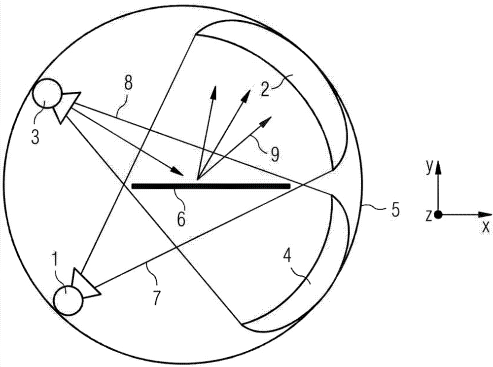
[0020] figure 1 Components of a dual-source computed tomography system with a suitably positioned target 6 for carrying out the proposed method are shown highly diagrammatically. In the drawing two X-ray systems A, B consisting of A-X-ray tube 1 and A-X-ray detector 2 and B-X-ray tube 3 and B-X-ray detector 4 can be recognized, which are arranged in the frame of the computed tomography system 5 on. Here, the two x-ray systems are arranged at an angle of 90° relative to each other in the direction of rotation of the gantry, such as from figure 1 as known from. The direction of rack rotation is indicated by a curved arrow.

[0021]In the present example, for the energy calibration of the A-X-ray detector 2 , the fluorescent target 6 is arranged in the X-ray beam 8 of the B-X-ray tube 3 in such a way that it is uniformly irradiated and hit by the resulting X-ray fluorescent radiation 9 A-X-ray detector 2 to be calibrated. In this case, the A-X-ray detector 2 is calibrated by...


PUM


Abstract

A method is disclosed for energy calibrating quantum-counting x-ray detectors in an x-ray installation. A target (6), for producing x-ray fluorescence radiation, is positioned between the first x-ray source (1) and first x-ray detector (2) and irradiated with x-radiation of the first x-ray source (1) in such a way that x-ray fluorescence radiation which strikes the second x-ray detector (4) from the target (6) is produced by the x-radiation of the first x-ray source (1). The second x-ray detector (4) is then energy calibrated by way of the x-ray fluorescence radiation of the target (6). The first x-ray detector (2) can be energy calibrated in the same way with the aid of the x-radiation of the second x-ray source (3). With the proposed method, the x-ray detectors of a dual-source CT x-ray installation can be calibrated with little expenditure under conditions close to those of the system.

Description

technical field [0001] The invention relates to a method for energy calibration of a quantum-counted X-ray detector in an X-ray system having at least two X-ray systems rotatable about a center of rotation, the X-ray systems being They are arranged with an angle offset from each other in the direction of rotation. Such x-ray systems are used in the field of computed tomography (CT) and are also known in design as dual-source computed tomography systems or dual-source C-arm x-ray systems. The invention also relates to a target for generating X-ray fluorescence radiation, which is suitable for carrying out the method. Background technique [0002] Quantum-counting X-ray detectors, also called photon-counting X-ray detectors, generally have an arrangement of detector elements (pixels) composed of a direct-conversion semiconductor material. The detected photons generate a charge pulse in the respective detector element, which is converted by the detector electronics into a mea...

Claims


Application Information

Patent Timeline
IPC IPC(8): G01T1/24
CPCG01T1/2985G01T7/005
Inventor M.艾肯西尔S.卡普勒E.克拉夫特B.克莱斯勒D.尼德罗纳S.沃思
Owner SIEMENS HEATHCARE GMBH
Learn More