
Light shielding device and light source device

A technology of a shading device and a light source device, which is applied to cooling/heating devices of lighting devices, electric light sources, lighting devices, etc., which can solve problems such as rising parts costs, achieve reduction of device costs, suppress parts costs, and suppress parts costs the effect of rising

Inactive Publication Date: 2013-09-18
GS YUASA INT LTD
View PDF8 Cites 2 Cited by
  • Summary
  • Abstract
  • Description
  • Claims
  • Application Information

AI Technical Summary

Problems solved by technology

[0012] In addition, as another method, in order to suppress the leakage of emitted light, it has also been tried to provide side covers on the inclined parts of the visor. However, in order to provide the inclined parts and side covers on a single plate, redundant work such as welding or molding processing is required. Processing, it is found that there are still problems that lead to an increase in the cost of parts

Method used


Image

  • Light shielding device and light source device
  • Light shielding device and light source device
  • Light shielding device and light source device

Examples


Embodiment Construction

[0061] Hereinafter, embodiments of the light source device of the present invention will be described based on the drawings.

[0062] In this embodiment, an ultraviolet irradiation device UR will be described as an example as a light source device.

[0063] The ultraviolet irradiating device UR of this embodiment is mounted on the printing head of the inkjet printing device for business use, and when the printing head is scanned to form an image, it moves together with the printing head and irradiates ultraviolet rays to the UV ink of the formed image. This makes the ink harden and dry instantly.

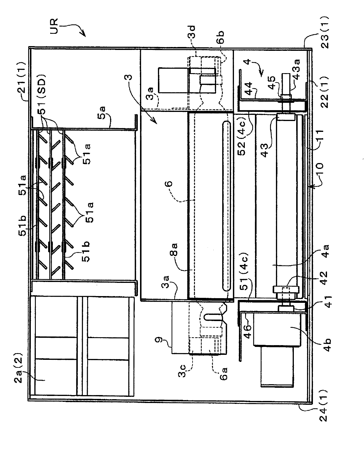
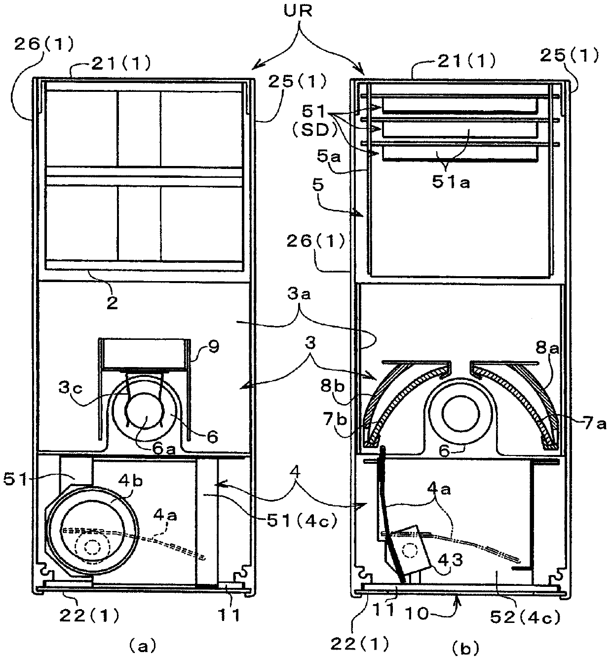
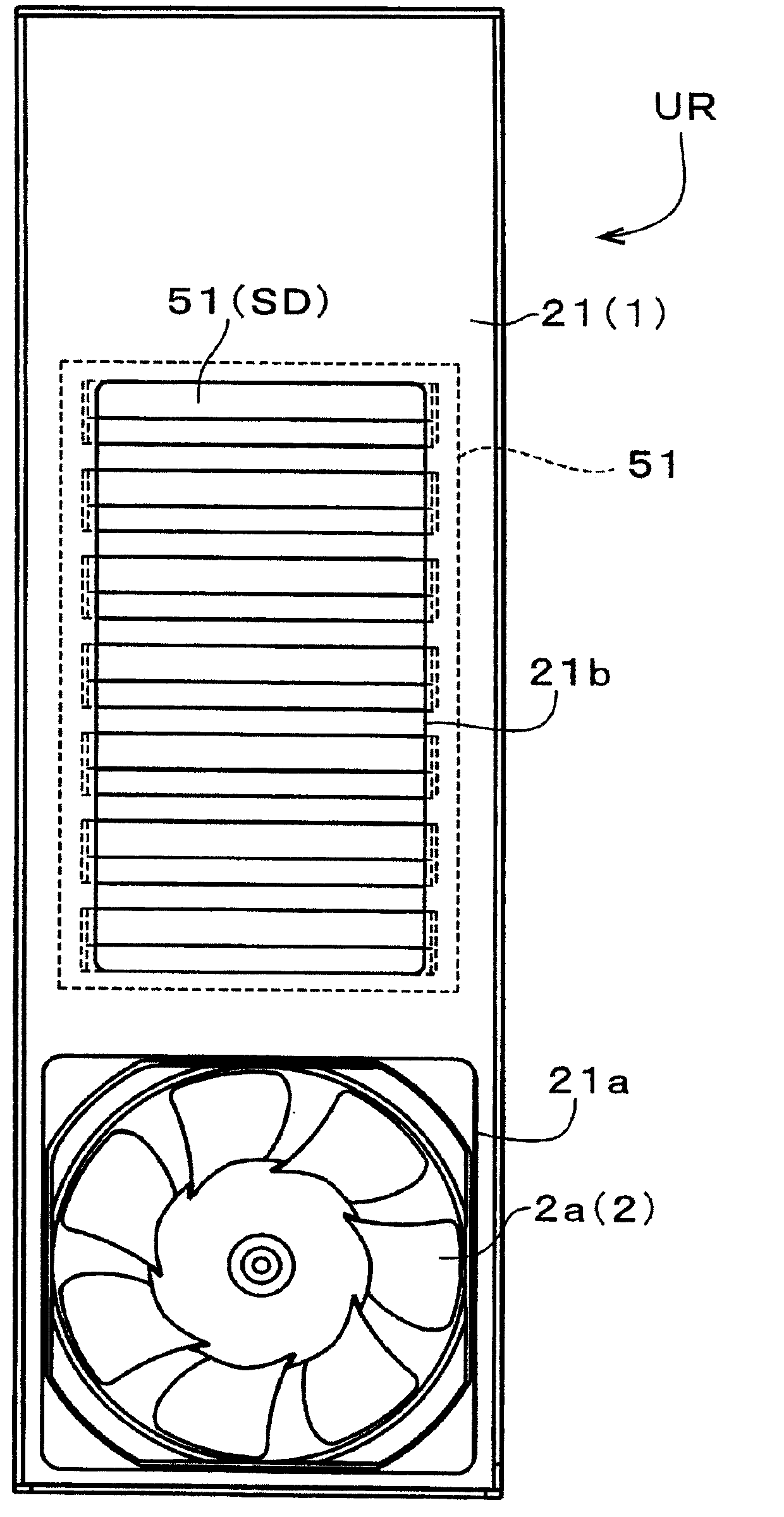
[0064] The ultraviolet irradiation device UR is as shown in the internal structure of the device frame 1 figure 1 As shown, it mainly includes a blower unit 2 , a lamp unit 3 , a shutter unit 4 and an exhaust unit 5 arranged in the device frame 1 . These units are connected to each other or fixed in the device housing 1 by fixing members not shown in the figure. It should be note...


PUM


Abstract

This light shielding device works to assure ventilation and sufficiently suppress leakage of light rays while suppressing increases in component costs as much as possible. Light shielding bodies (51) are provided for allowing ventilation and shielding from the passage of light rays. The light shielding bodies (51) are constituted by being provided with a plurality of sloped attitude parts (51a) bent with a sloped attitude and partially separated from a flat surface part of a sheet material in a state of being lined up in a specified direction with substantially the same attitudes. The light shielding bodies (51), which have the same shape, are disposed in an attitude such that the direction in which the sloped attitude parts (51a) on each of the light shielding bodies (51) are lined up, and three or more are lined up in the direction of the thickness of the flat surface parts. The constitution is such that the plurality of light shielding bodies (51) is lined up in a state where the orientation of the slope of the sloped attitude parts (51a) is alternately reversed.

Description

technical field [0001] The present invention relates to a light-shielding device provided with a light-shielding body that allows ventilation and blocks the passage of light, and also relates to a light source device in which a light source lamp is provided in a device frame for cooling the light source lamp. The exhaust port or air intake port for exhausting or inhaling the cooling air is formed on the side surface of the device frame, and the exhaust port or air intake port is equipped with a device that allows the cooling air to pass through and is used to cover A light-shielding body for the emitted light of the light source lamp. Background technique [0002] In the light source device equipped with the shading device, as a device using a light source lamp that mainly emits visible light, for example, a projector, etc., as a device that uses a light source lamp (that is, an ultraviolet lamp) that mainly emits ultraviolet light, for example, there is ultraviolet irradiat...

Claims


Application Information

Patent Timeline
Patent Type & Authority Applications(China)
IPC IPC(8): F21S2/00B41J2/01F21V29/02G03B21/14G03B21/16H05K7/20
CPCG03B21/16H05K5/0213G03B21/20
Inventor 角波雅之
Owner GS YUASA INT LTD
Learn More