Die-bonding adhesive pressing method and pressurizing device

A technology of pressurizing device and die-bonding glue, which is applied in the direction of electrical components, circuits, semiconductor devices, etc., can solve the problems of reducing the thickness of die-bonding glue and reducing the thermal resistance of the LED system, so as to reduce the thermal resistance and reduce the heat conduction path , the effect of reducing the thickness

Active Publication Date: 2016-08-03
安徽锐拓电子有限公司
View PDF5 Cites 0 Cited by
  • Summary
  • Abstract
  • Description
  • Claims
  • Application Information

AI Technical Summary

Problems solved by technology

[0005] The purpose of the present invention is to provide a die-bonding adhesive pressing method and a pressurizing device, which can reduce the thickness of the die-bonding adhesive, aiming to solve the existing problem of how to reduce the thermal resistance of the LED system

Method used


Image

  • Die-bonding adhesive pressing method and pressurizing device
  • Die-bonding adhesive pressing method and pressurizing device
  • Die-bonding adhesive pressing method and pressurizing device

Examples


Embodiment 1

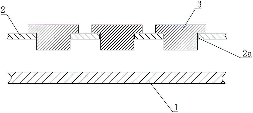
[0041] In this embodiment, an LED bracket with a cup structure is taken as an example to illustrate the present invention. Such as figure 1 As shown, the pressurizing device of this embodiment includes a fixed working platform 1, a mobile platform 2, a pressurizing block 3 and a moving control component (not shown). The fixed working platform 1 is used to place the LED bracket, and the mobile platform 2 is located above the fixed working platform 1, and the mobile platform 2 can move under the control of the mobile control part. The fixed working platform 1 and the mobile platform 2 of this embodiment are both metal plates, and the mobile platform 2 is processed with a plurality of placement holes 2a, and the placement holes 2a are distributed on the mobile platform 2 at intervals, and the placement holes 2a can be in the form of a dot matrix or a line. Arranged in an array, the position of the placement hole 2a corresponds to the position of the LED chip on the LED bracket. ...

Embodiment 2

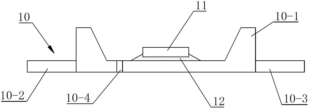
[0052] Such as Figure 8 As shown, the LED bracket of this embodiment does not have a bowl structure, and the LED bracket 10 is provided with a positive electrode 10-2 and a negative electrode 10-3, and an insulating tape 10 is placed between the positive electrode 10-2 and the negative electrode 10-3. -4 quarantined. The LED bracket 10 has a die-bonding area where the LED chip 11 is fixed, and the LED chip 11 is fixed on the LED bracket 10 through a die-bonding glue 12 .

[0053] refer to Figure 9 , the bottom surface of the mobile platform 2 of the pressurizing device in this embodiment is provided with a height limiting block 2b, and the height limiting block 2b is integrally processed and formed with the mobile platform 2. The height limiting block 2b can also be arranged on the mobile platform by welding or other connection methods. Platform 2 underside. A plurality of placement holes 2a are processed on the mobile platform 2, and the placement holes 2a are distribute...


PUM


Abstract

The invention discloses a die attach adhesive pressing method and a pressurizing device used for thinning the die attach adhesive of an LED (light emitting diode) after die attaching. The pressurizing device comprises a fixed working platform, a mobile platform, a mobile control part and a pressurizing block, wherein the pressurizing block is arranged on the mobile platform, an LED chip is fixedly arranged on an LED bracket through die attach adhesive, and the LED bracket after die attaching is fixedly arranged on the fixed working platform; the pressurizing block moves downwards to press the LED chip, so as to press the die attach adhesive, and the pressurizing block is driven by the mobile part to move downwards; a heating device is started to heat the die attach adhesive, after the die attach adhesive is cured and sized, the pressurizing block is removed, and the machining of the next step is carried out. According to the die attach adhesive pressing method and the pressurizing device, the pressurizing device is adopted to carry out pressing action on the LED chip, the thickness of the die attach adhesive is reduced under the pressure effect of the pressurizing device, the die attach adhesive is heated and the pressurizing device is removed until the die attach adhesive is cured and sized, so that the thermal resistance of a lamp bead of the LED is reduced, and the reliability of the LED is improved.

Description

technical field [0001] The invention belongs to the technical field of light-emitting diode packaging, and in particular relates to a method and a device for reducing the thickness of the die-bonding adhesive by pressurizing after the LED (Light-Emitting Diode, hereinafter referred to as LED) wafer is die-bonded. Background technique [0002] At present, the heat problem in LED packaging technology has become a common problem in the industry. All enterprises are committed to how to make the heat generated by the LED chip can be effectively and quickly led to the air, so as to improve the reliability of the LED lamp bead, and reduce the thermal resistance. The key technology to solve this problem. [0003] Reducing the thermal resistance of the entire system of LED lamp beads needs to start from every link. As we all know, the link with the largest thermal resistance of LED lamp beads is the die-bonding glue, especially the small and medium-power LEDs that use insulating glu...

Claims


Application Information

Patent Timeline
Patent Type & Authority Patents(China)
IPC IPC(8): H01L33/48H01L33/54
Inventor 陈健平
Owner 安徽锐拓电子有限公司
Why Eureka
Try Eureka