
Optical fiber current sensing system

A technology of optical fiber current sensing and current, applied in voltage/current isolation, measuring current/voltage, measuring electrical variables, etc., can solve problems such as application limitations, achieve simple and convenient installation process, improve polarization performance, and facilitate assembly

Inactive Publication Date: 2013-09-18
XUNDI SCI & TECH HUBEI PROV
View PDF6 Cites 6 Cited by
  • Summary
  • Abstract
  • Description
  • Claims
  • Application Information

AI Technical Summary

Problems solved by technology

It can be seen that the existing optical fiber current sensor cannot be installed on site with openings, so its application in the fields of metallurgy and chemical industry is limited.

Method used


Image

  • Optical fiber current sensing system
  • Optical fiber current sensing system
  • Optical fiber current sensing system

Examples


Embodiment Construction

[0037] Embodiments of the present invention will be described in more detail below with reference to the accompanying drawings. Throughout the drawings, the same reference numerals denote the same elements.

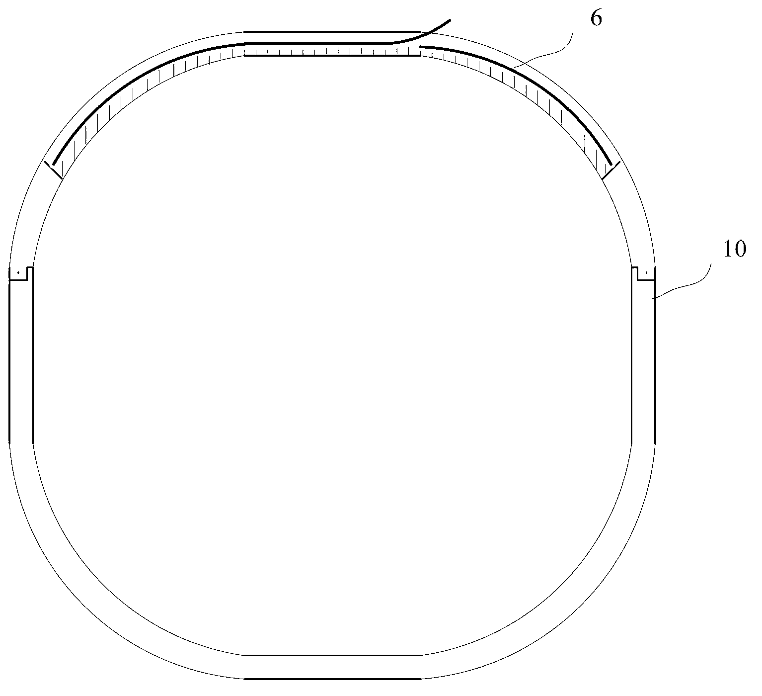
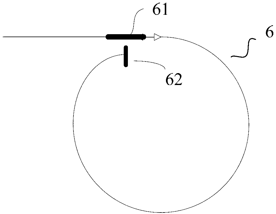
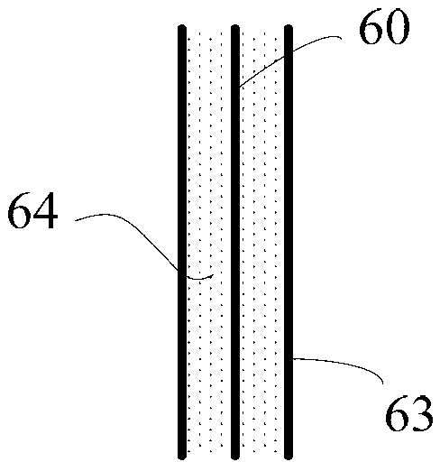
[0038] In order to enable the sensing optical fiber to be installed with openings on site, an embodiment of the present invention provides an optical fiber current sensing device for measuring current passing through a conductor. Such as figure 1 As shown, the fiber optic current sensing device includes a sensing fiber 6 and a bracket 10 for installing the sensing fiber. The sensing fiber 6 includes an optical fiber and a flexible protective sheath covering the optical fiber. The bracket 10 includes a first portion and a second portion each having a fiber optic groove. The first part and the second part are detachably connected to form a closed ring structure surrounding the conductor under test, and the fiber groove of the first part and the fiber groove of the second...


PUM


Abstract

The invention provides an optical fiber current sensing system which comprises a photoelectric detector, a signal processing unit, as well as a light source, a Y-shaped wave guide, a 45-degree welding point, a strip-shaped waveguide modulator, a polarization maintaining optical fiber and an optical fiber current sensing device which are sequentially connected with one another, wherein the Y-shaped wave guide is provided with a first branching end, a second branching end and a combining end, and is used for converting a light beam which is received from the light source through the first branching end into a linearly polarized light, receiving the light beam which is returned from the optical fiber current sensing device and carries the conductor current information from the combining end, and outputting from the second branching end; and the photoelectric detector is used for detecting the intensity of interference light outputted from the second branching end of the Y-shaped wave guide, converting the light intensity information into an electric signal, and transmitting to the signal processing unit. The optical fiber current sensing system adopts a double-waveguide structure, the polarization performance of a light path can be improved due to the Y-shaped wave guide, and the optical phase can be modulated due to the strip-shaped waveguide modulator, so that the light path has the advantages of being simple in structure and high in light path polarization stability.

Description

[0001] This application is a divisional application with a patent application number of "201010150176.7", an application date of "April 12, 2010", and an invention title of "Optical Fiber Current Sensing Device and Optical Fiber Current Sensing System". technical field [0002] The invention relates to optical fiber current sensing technology, in particular to an optical fiber current sensing system. Background technique [0003] Current sensors or transformers are important equipment for current detection in the fields of metallurgy, chemical industry, and electric power. Their long-term stability, reliability, and safety are closely related to the safe and stable operation of the power supply system. [0004] Currently, the reported fiber optic current sensors based on the Faraday effect are used in current measurement due to their large measurement range and high precision. This fiber optic current sensor mainly uses Ampere's loop law and Faraday's magneto-optical effect ...

Claims


Application Information

Patent Timeline
Patent Type & Authority Applications(China)
IPC IPC(8): G01R19/00G01R15/24G01K11/32
Inventor 郭嘉昕
Owner XUNDI SCI & TECH HUBEI PROV
Learn More