Stage lamp thermal system

A technology for stage lamps and hot zones, which is applied to lighting and heating equipment, cooling/heating devices of lighting devices, lighting devices, etc., and can solve problems such as burnout and fan failure

Active Publication Date: 2015-07-08
GUANGZHOU HAOYANG ELECTRONICS CO LTD
View PDF5 Cites 2 Cited by
  • Summary
  • Abstract
  • Description
  • Claims
  • Application Information

AI Technical Summary

Problems solved by technology

However, due to the smaller installation space of the fan after miniaturization, the heat is more concentrated, and the temperature of the fluid passing through the fan will be quite high, which often causes the fan to fail and burn out.

Method used


Image

  • Stage lamp thermal system
  • Stage lamp thermal system
  • Stage lamp thermal system

Examples


Embodiment 1

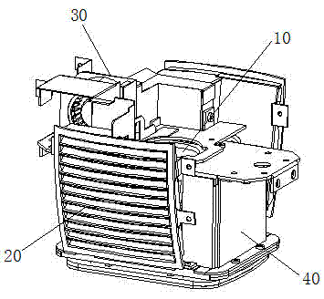
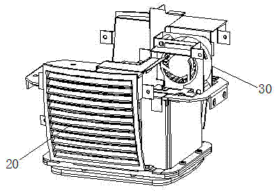
[0036] Such as Figure 1 to Figure 8 Shown is the first embodiment of the stage light thermal system of the present invention, as figure 1 , figure 2 As shown, it includes a light emitting unit 10, an air inlet chamber 20, an air blast chamber 30 and an air outlet chamber 40, as image 3 , Figure 4 As shown, the air inlet cavity 20 is provided with a system air inlet 21, a fan 22 and a flow distribution mechanism 23, as Figure 6 As shown, the air distribution mechanism 23 divides the air inlet cavity 20 into a cold area L and a hot area R, wherein the system air inlet 21 is located in the cold area L, a part of the fan 22 is located in the cold area L, and the other part is located in the hot area R, and the cold area L is connected to the air blowing chamber 30 and the air outlet chamber 40 , the hot zone R is connected to the air outlet chamber 40 , the air blast chamber 30 is connected to the air outlet chamber 40 , and the light emitting unit 10 is installed in the a...

Embodiment 2

[0042] Such as Figure 9 Shown is the second embodiment of the stage light thermal system of the present invention. As an improvement to Embodiment 1, the stage light thermal system of this embodiment further includes a heat insulating element 50 arranged outside the light emitting unit 10, and the heat insulating element 50 separates the light Functional components within the lamp cavity of the unit and thermal system. Among them, the functional components include color chip disk, pattern disk, CMY color mixing system, etc.

[0043] Further, the heat insulation element 50 is 8-15 mm away from the light-emitting unit 10 and covers the top of the light-emitting unit at an angle of 5-30° with respect to the installation plane of the light-emitting unit 10 .

[0044] The thermal system of the stage light in the embodiment of the present invention is arranged around the light-emitting unit to form an air inlet chamber, an air blast chamber, and an air outlet chamber. In the low ...


PUM


Abstract

The invention relates to the technical field of illuminating lamps, in particular to a stage lamp thermal system, which comprises a lighting unit, an air-in chamber, an air-blast chamber and an air-out chamber, wherein an air inlet for the system, a fan and a shunting mechanism are arranged in the air-in chamber; the shunting mechanism divides the air-in chamber into a cold zone and a hot zone, and part of the fan is in the cold zone and the other part is in the hot zone; the air inlet for the system is in the cold zone communicated with the air-blast chamber; both the cold zone and the hot zone are communicated with the air-out chamber; the air-blast chamber is communicated with the air-out chamber; and the lighting unit is arranged between the air-blast chamber and the air-out chamber. The stage lamp thermal system has the characteristics of sucking air and exhausting air forcibly, has the hot zone and the cold zone which are obvious, ensures that all subsystems in the lamp is in reasonable operating temperature range, solves the difficult thermal problems caused by that the stage lamp adopts miniaturized lighting luminaire, but the power is unceasingly boosted, prolongs the service life of the stage lamp and improves the working reliability of the luminaire.

Description

technical field [0001] The present invention relates to the technical field of lighting fixtures, and more specifically, to a stage lighting thermal system. Background technique [0002] With the continuous development of science and technology, people require more and more integration and miniaturization of the instruments and equipment used. As a professional lighting equipment in the performing arts industry, stage lights have a compact structure after miniaturization, which brings convenience to transportation and installation. However, the power of stage lights is relatively large, which generates a lot of heat, and the bulbs have certain temperature range requirements when they work. For example, when the Philips platinum 5R bulb is working normally, the surface temperature of the luminous sphere is 770~930°C. Excessive bulb temperature will directly lead to a series of problems such as reduced light source efficiency, thermal erosion and burning of electronic compone...

Claims


Application Information

Patent Timeline
Patent Type & Authority Patents(China)
IPC IPC(8): F21V29/67F21W131/406
Inventor 蒋伟楷
Owner GUANGZHOU HAOYANG ELECTRONICS CO LTD
Why Eureka
Try Eureka