
Parallel multi-dimensional swing wave power generation device

A multi-dimensional swing and wave power generation technology, applied in ocean energy power generation, engine components, machines/engines, etc., can solve the problems of reduced swing capacity, energy consumption, and destruction of fan-shaped floats, reducing the risk of seawater corrosion and improving Period of use, effect of improving power generation efficiency

Inactive Publication Date: 2015-10-14
SHANGHAI JIAOTONG UNIV
View PDF7 Cites 4 Cited by
  • Summary
  • Abstract
  • Description
  • Claims
  • Application Information

AI Technical Summary

Problems solved by technology

[0002] After searching the prior art, it is found that the fan-shaped tank wave power generation device (Chinese Patent No. ZL.200920002647.X) that converts the impact energy of waves into electric energy has the following deficiencies: 1. The fan-shaped tank is located on the shore foundation, and the waves are finally By the time the unit is reached, the energy has already been dissipated so much that the unit is not effectively using the energy of the ocean waves to generate electricity
2. After the tide rises, the swing ability of the fan-shaped buoy decreases, and the wave cannot be effectively used to generate electricity
[0003] Investigate the existing swing-type wave power generation device. The utility model patent swing-type wave power generation device (China Patent No. 201020587628.3) uses waves to impact the swing plate, and transmits it to the flywheel on the main shaft through the gear on the swing shaft, and drives the main shaft to rotate in one direction. Finally, the motion is transmitted to the generator to generate electricity, but the device has the following disadvantages: 1. The direction of the waves is irregular
The device does not use energy efficiently
2. When the waves hit the flat plate, it will cause a certain degree of impact on the swing shaft. This kind of impact is repeated, and the continuous fatigue accumulation forms fatal damage.

Method used


Image

  • Parallel multi-dimensional swing wave power generation device
  • Parallel multi-dimensional swing wave power generation device
  • Parallel multi-dimensional swing wave power generation device

Examples


Embodiment Construction

[0027] The present invention will be described in detail below in conjunction with specific embodiments. The following examples will help those skilled in the art to further understand the present invention, but do not limit the present invention in any form. It should be noted that those skilled in the art can make several modifications and improvements without departing from the concept of the present invention. These all belong to the protection scope of the present invention.

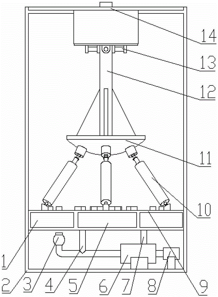
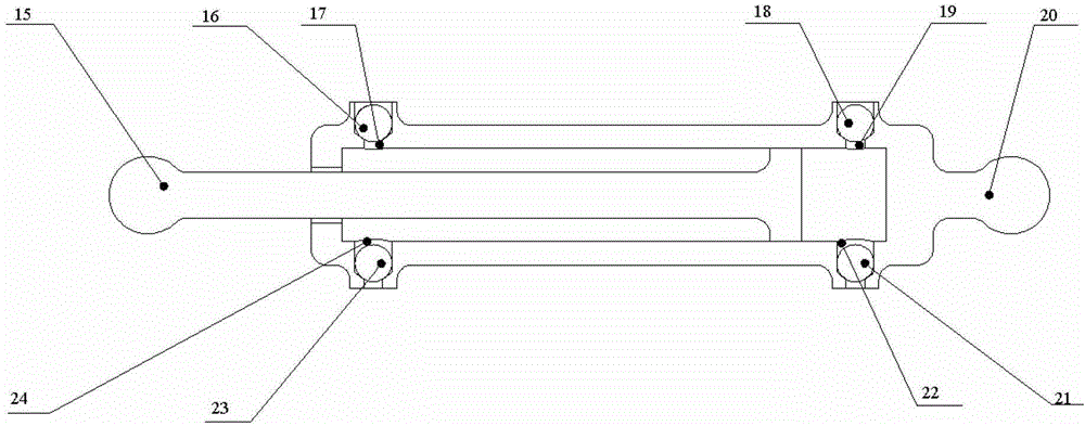
[0028] Such as figure 1 and Figure 5 As shown, in this example, the parallel multi-dimensional swing wave power generation device mainly includes a floating body 2 and an accumulator 3 arranged inside the floating body, a hydraulic motor 6, a generator 8, a fuel tank 9, six hydraulic cylinders 10, and a swing platform 11 , a swing rod 12, a two-dimensional rotating hinge 13 and a sealing cover 14, wherein the sealing cover 14 is fixedly connected on the floating body 2 through a screw connection...


PUM


Abstract

The invention discloses a novel parallel multidimensional oscillating sea wave power generation device. The novel parallel multidimensional oscillating sea wave power generation device comprises a floater, and a sealing cover plate, a two-dimensional rotating hinge, an oscillating rod, an oscillating platform, six hydraulic cylinders, an oil tank, a hydraulic motor, a power generator and an energy accumulator which are all arranged in the floater, wherein the sealing cover plate is fixedly connected to a protruding eave of the floater; the oil tank is fixedly connected to the floater; one end of the two-dimensional rotating hinge is fixedly connected to the sealing cover plate and the other end is connected to the oscillating rod; one end of the oscillating rod penetrates through the sealing cover plate to be fixedly connected to an external device and the other end is fixedly connected to the oscillating platform; the six hydraulic cylinders are connected in parallel to work; the two ends of the six hydraulic cylinders are respectively hinged to the oscillating platform and the oil tank through spherical hinges; the oil tank is connected with the hydraulic motor through a flow-dividing pipe and a return pipe; the power generator is connected with the hydraulic motor; the power generator and the hydraulic motor are arranged on the bottom surface of the floater; the energy accumulator is connected with the hydraulic motor. The novel parallel multidimensional oscillating sea wave power generation device has the advantages of long service life, low maintenance cost, low environmental pollution, capability of fully absorbing sea wave energy, high power generation efficiency and the like.

Description

technical field [0001] The invention relates to a wave power generation system, in particular to a parallel multi-dimensional swing wave power generation device. Background technique [0002] After searching the prior art, it is found that the fan-shaped tank wave power generation device (Chinese Patent No. ZL.200920002647.X) that converts the impact energy of waves into electric energy has the following deficiencies: 1. The fan-shaped tank is located on the shore foundation, and the waves are finally By the time the unit is reached, a lot of energy has already been consumed, so the unit is not effectively using the energy of the ocean waves to generate electricity. 2. After the high tide, the swing ability of the fan-shaped buoys decreases, and the waves cannot be effectively used to generate electricity. [0003] Investigate the existing swing-type wave power generation device. The utility model patent swing-type wave power generation device (China Patent No. 201020587628...

Claims


Application Information

Patent Timeline
Patent Type & Authority Patents(China)
IPC IPC(8): F03B13/22
CPCY02E10/38Y02E10/30
Inventor 马春翔陈康郑茂琦陈伟聪高峰王志波
Owner SHANGHAI JIAOTONG UNIV
Learn More