Elastic spiral pipe type fluid engine
A spiral tube and engine technology, applied in the direction of machines/engines, liquid variable displacement machinery, mechanical equipment, etc., can solve the problems of complex engine structure and energy consumption, and achieve the effect of simple structure, large output power and reliable operation
- Summary
- Abstract
- Description
- Claims
- Application Information
AI Technical Summary
Problems solved by technology
Method used
Image
Examples
Embodiment 1
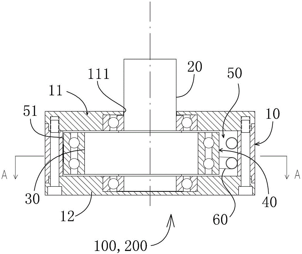
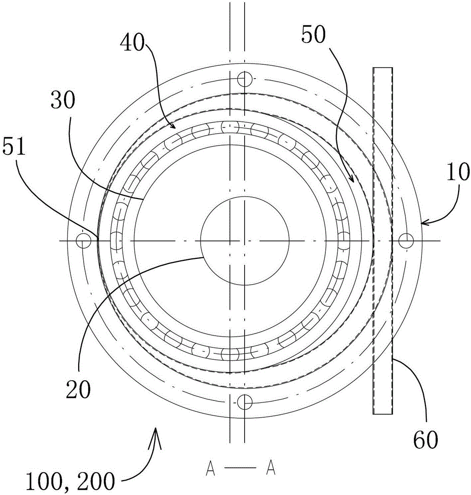
[0024] refer to figure 1 , figure 2 , The elastic helical tube type fluid motor 100 of the present invention includes a cylindrical body 10 , a central shaft 20 , an eccentric wheel 30 , a pressure bearing 40 and a helical tube 60 . The fluids described in this embodiment are liquid and gas.
[0025] Such as figure 1 , figure 2 As shown, the cylindrical body 10 is made of stainless steel, and its two ends are fixed with end caps 11, 12 by bolts, and the joints between the end caps 11, 12 and the cylindrical body 10 are sealed with sealing rings. A central shaft hole 111 for passing the central shaft 20 is provided at the center of one of the end caps 11 . The central shaft 20 is supported by a bearing disposed in the central shaft hole 111 and protrudes from the central shaft hole.
[0026] Such as figure 1 , figure 2 , Figure 4 , Figure 5 As shown, a central axis 20 is provided in the cylindrical body, and the central axis 20 is coaxial with the cylindrical body...
Embodiment 2
[0032] In this embodiment, by reversely setting the elastic helical tube type fluid motor in Embodiment 1, a helical tube type fluid pump or a gas compressor can be formed.
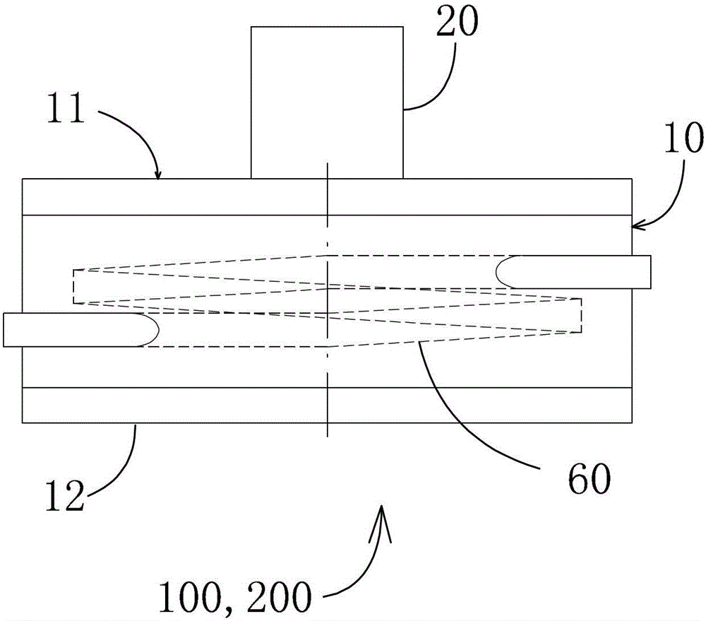
[0033] refer to Figure 1-6 , the helical tube type fluid pump or gas compressor 200 includes a cylindrical body 10 , a central shaft 20 , an eccentric wheel 30 , a pressure bearing 40 and a helical tube 60 .
[0034] Such as Figure 1-6, the fluid pump or gas compressor 200 includes a cylindrical body 10, in which a central shaft 20 coaxial with the cylindrical body is provided, and the difference from embodiment 1 is that the central shaft 20 is connected to the motor (Fig. not shown in ), and is driven by a motor to rotate. An eccentric wheel 30 is arranged on the central shaft 20, and a pressure bearing 40 is fixed on the eccentric wheel. A gap 50 that changes along the circumferential direction is formed between the outer ring of the pressure bearing and the inner wall of the cylinder. There is an...
PUM
 Abstract
Description
Claims
Application Information
 - R&D Engineer
- R&D Manager
- IP Professional
- Industry Leading Data Capabilities
- Powerful AI technology
- Patent DNA Extraction
Browse by: Latest US Patents, China's latest patents, Technical Efficacy Thesaurus, Application Domain, Technology Topic, Popular Technical Reports.
© 2024 PatSnap. All rights reserved.Legal|Privacy policy|Modern Slavery Act Transparency Statement|Sitemap|About US| Contact US: help@patsnap.com


