
Sports stand hanging formwork support formwork

A stand and hanging formwork technology, which is applied in the field of hanging formwork for pouring sports stands, can solve the problems of inconvenient construction turnover, affecting the appearance and quality of stands, and low structural strength and rigidity, so as to improve the appearance quality and simple structure , the effect of high strength and stiffness grades

Active Publication Date: 2016-03-02
TAIXING FIRST CONSTR INSTALLATION
View PDF8 Cites 0 Cited by
  • Summary
  • Abstract
  • Description
  • Claims
  • Application Information

AI Technical Summary

Problems solved by technology

The formwork of the traditional steps is mostly based on the ordinary stair step structure. In the patent No. CN201210229153.4, a fully enclosed staircase formwork component is used to arrange the steps above the bottom formwork between the left formwork and the right formwork. For several unit formworks with the same number, steel beading is arranged on the top of all unit formworks, and pull bolts are set between the steel beading and the bottom formwork, and the formwork components are fixed before pouring, such as using a closed formwork with all-round protection Due to the large span, height and width of the stadium tube stand, the required formwork for pressing and the bolts required for tensioning consume a lot of equipment, which is not convenient for construction turnover and increases construction costs, and the bottom formwork is connected by bolts. The overall structural strength and rigidity of the formwork members are low, and it is easy to press or tighten on the steps of the stands to form dents, which affects the appearance and quality of the stands

Method used


Image

  • Sports stand hanging formwork support formwork

Examples


Embodiment Construction

[0016] The present invention will be further described below in conjunction with accompanying drawing.

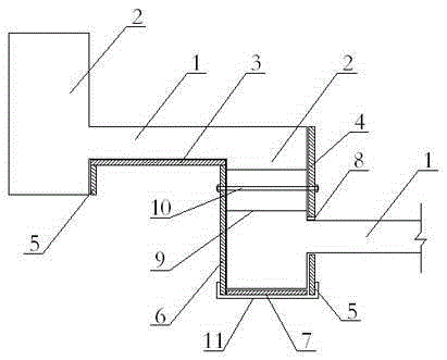
[0017] figure 1 As shown, a suspension formwork for a sports stand includes a stand plate bottom formwork 3, an upper formwork 4 on the front side of the stand beam, a lower formwork 5 on the front side of the stand beam, a formwork 6 on the back side of the stand beam, a bottom formwork 7 for the stand beam, and a joist 8 , short steel bar 9, screw rod 10 and beam mold clamp 11, the bottom formwork 3 of the stand is arranged on the bottom of the stand 1, the upper formwork 4 on the front side of the stand beam and the lower formwork 5 on the front side of the stand beam are respectively arranged on the front side of the stand beam 2 The upper part and the lower part, the back side formwork 6 of the stand beam is arranged on the back side of the stand beam 2, and the bottom formwork 7 of the stand beam is arranged on the bottom of the stand beam 2; The lower formwork is su...


PUM


Abstract

The invention relates to a suspension formwork for a sports stand. The bottom formwork of the stand plate is arranged at the bottom of the stand plate, the upper and lower formworks on the front side of the stand beam are respectively set on the upper and lower parts of the front side of the stand beam, and the back side formwork of the stand beam is set on the stand beam. On the back side, the bottom formwork of the stand beam is set at the bottom of the stand beam; one end of the bottom formwork of the stand plate is supported by the lower formwork on the front side of the stand beam at the lower part of the front side of the stand beam of the upper level, and the other end of the bottom formwork of the stand plate passes through the stand beam of the next level The back side formwork of the stand beam is supported on the back side. The two ends of the bottom formwork of the stand beam are respectively matched with the bottom of the lower formwork on the front side of the stand beam and the bottom end of the back side formwork of the stand beam. The formwork and the formwork on the back side of the stand beam are tensioned and connected to the stand beam through screw rods. Its structure is simple, the formwork is easy to operate and stable, and it can effectively take into account the quality of the stands, construction efficiency and energy consumption.

Description

technical field [0001] The invention relates to a hanging formwork, in particular to a hanging formwork for pouring sports stands. Background technique [0002] Most of the existing stadium stands use steps with large span, height and width. Such steps need to be cast to ensure the appearance and quality of the steps. The formwork of the traditional steps is mostly based on the ordinary stair step structure. In the patent No. CN201210229153.4, a fully enclosed staircase formwork component is used to arrange the steps above the bottom formwork between the left formwork and the right formwork. For several unit formworks with the same number, steel beading is arranged on the top of all unit formworks, and pull bolts are set between the steel beading and the bottom formwork, and the formwork components are fixed before pouring, such as using a closed formwork with all-round protection Due to the large span, height and width of the stadium tube stand, the required formwork for p...

Claims


Application Information

Patent Timeline
Patent Type & Authority Patents(China)
IPC IPC(8): E04G13/06
Inventor 陈钧颐田国生
Owner TAIXING FIRST CONSTR INSTALLATION
Learn More