Two-way check valve easy to adjust
A two-way one-way valve and regulating needle valve technology, which is applied in the direction of control valves, air release valves, brake components, brakes, etc., can solve the problem of slow gas discharge from the brake chamber, difficulty in balancing the braking force of multiple wheels, and The air flow cannot be adjusted, etc., to achieve the effect of low production cost, rapid release of the brake process, and good braking effect
- Summary
- Abstract
- Description
- Claims
- Application Information
AI Technical Summary
Problems solved by technology
Method used
Image
Examples
Embodiment 1
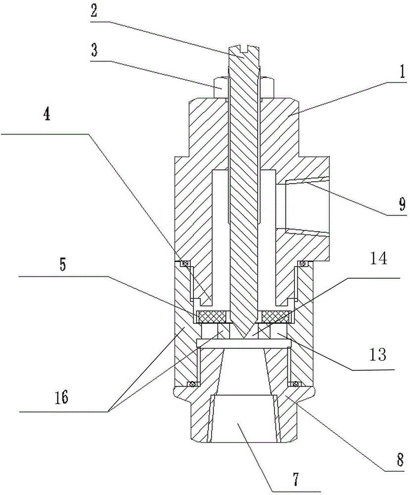
[0026] Embodiment one: as attached figure 1 , Figure 4 , Figure 5 , Figure 6 As shown, the easy-to-adjust two-way one-way valve includes a valve body 1, a built-in exhaust passage 10 in the valve body 1, and an adjusting needle valve is arranged on the upper side of the valve body 1, and the adjusting needle valve includes a part of the exhaust In the air passage 10, the flow regulating rod 2 partially protruding from the valve body 1, and the lock nut 3 arranged outside the valve body 1 and used in conjunction with the flow regulating rod 2 are connected to the lower side of the valve body 1 through the middle casing 16. A joint 8, the joint 8 is provided with an air outlet 7 communicating with the exhaust passage 10, correspondingly, the side wall of the valve body 1 is provided with an air inlet 9 communicating with the exhaust passage 10, the valve body 1 and the joint The movable film 5 adjusted by adjusting the needle valve is arranged in the middle housing 16 betw...
Embodiment 2
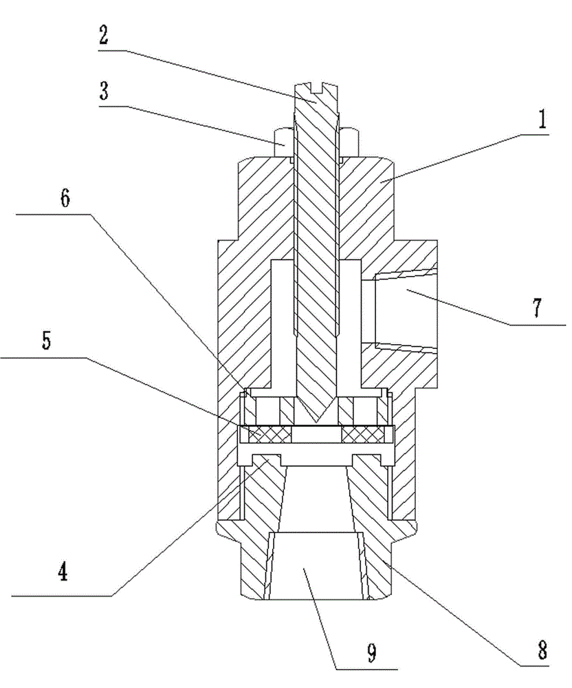
[0028] Embodiment two: as attached figure 2 , Figure 5 , Figure 6 , Figure 7 As shown, the easy-to-adjust two-way one-way valve includes a valve body 1, a built-in exhaust passage 10 in the valve body 1, and an adjusting needle valve is arranged on the upper side of the valve body 1, and the adjusting needle valve includes a part of the exhaust In the air passage 10, the flow regulating rod 2 that partially protrudes from the valve body 1, the lock nut 3 that is arranged on the outside of the valve body 1 and used in conjunction with the flow regulating rod 2, is connected with a joint 8 on the lower side of the valve body 1, and the joint 8 is provided with an air inlet 9 communicating with the exhaust passage 10. Correspondingly, the side wall of the valve body 1 is provided with an air outlet 7 communicating with the exhaust passage 10. The connection between the valve body 1 and the joint 8 is set There are movable film 5 and adjusting piece 6 that are regulated by ...
Embodiment 3
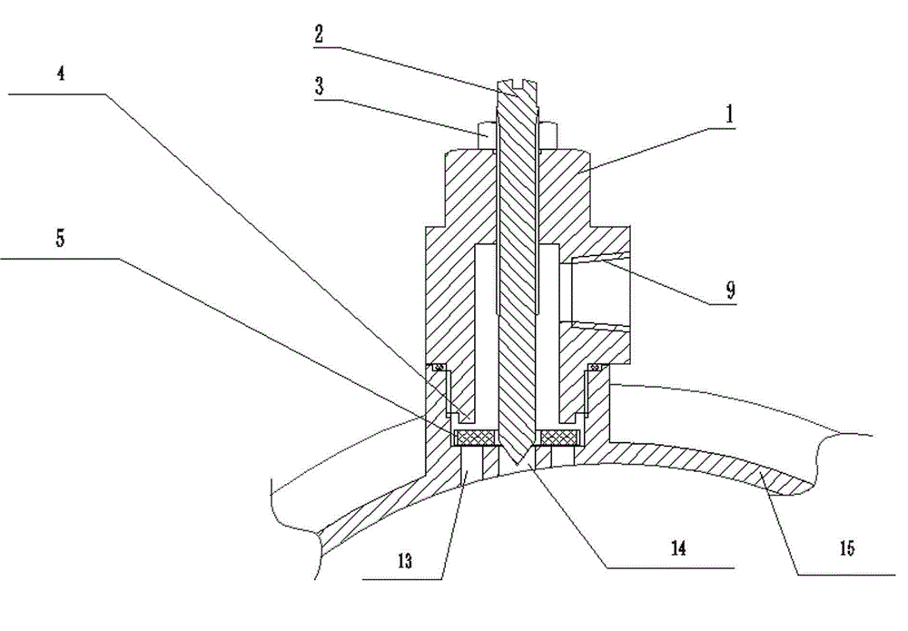
[0032] Embodiment 3, as attached image 3 , Figure 5 , Figure 6 As shown, an easily adjustable intake and exhaust valve of the brake chamber includes a valve body 1, a built-in exhaust passage 10 in the valve body 1, and an adjusting needle valve is arranged on the upper side of the valve body 1, and the adjusting needle valve includes a part Into the exhaust passage 10, the flow regulating rod 2 partially protruding from the valve body 1, the lock nut 3 arranged outside the valve body 1 and used in conjunction with the flow regulating rod 2, the brake gas is connected to the lower side of the valve body 1 Chamber 15, the side wall of the valve body 1 is provided with an air inlet 9 connected to the exhaust passage 10, and correspondingly, the connection between the brake chamber 15 and the valve body 1 is uniformly provided with a group of intake and exhaust holes, Between the valve body 1 and the intake and exhaust hole groups of the brake air chamber 15, there is an adj...
PUM
 Abstract
Description
Claims
Application Information
 - R&D
- Intellectual Property
- Life Sciences
- Materials
- Tech Scout
- Unparalleled Data Quality
- Higher Quality Content
- 60% Fewer Hallucinations
Browse by: Latest US Patents, China's latest patents, Technical Efficacy Thesaurus, Application Domain, Technology Topic, Popular Technical Reports.
© 2025 PatSnap. All rights reserved.Legal|Privacy policy|Modern Slavery Act Transparency Statement|Sitemap|About US| Contact US: help@patsnap.com


