Received signal strength indicator circuit and method for correcting deviation thereof

A technology of received signal strength and signal strength indication, applied in the field of received signal strength indication circuit, can solve the problems of RSSI output deviation, large chip area, influence system deviation, etc., and achieve the effect of correcting system deviation

Inactive Publication Date: 2013-09-11
WUXI ZETAI MICROELECTRONICS
View PDF4 Cites 2 Cited by
  • Summary
  • Abstract
  • Description
  • Claims
  • Application Information

AI Technical Summary

Problems solved by technology

[0003] For example, the RSSI circuit 1 includes 11 stages of limiting amplifiers 11, each stage can amplify the signal by 6db, then the signal passing through the RSSI circuit 1 can be amplified by 66dB, so that the offset signal in the RSSI circuit 1 can be amplified many times, thereby Make the output RSSI value wrong, reduce the sensitivity of the receiver, and need to make deviation correction
[0004] One of the methods for correcting offset signals in the prior art is as figure 2 As shown, an analog deviation correction circuit 21 is connected to the input end of the RSSI circuit 10, and the deviation signal output by the comparison output end of the RSSI circuit 10 obtains the system deviation after passing through an RC filter circuit 22 to filter useful signals, and then the system The deviation is negatively fed back to the analog deviation correction circuit 21 for correction. However, since the RC filter circuit 21 filters useful signals, the required resistance and capacitance area are too large, which will slow down the startup speed and require a large chip area.
[0005] And when receiving the signal, the output of the received signal will affect the feedback of the system deviation, which will cause some deviation in the RSSI output

Method used


Image

  • Received signal strength indicator circuit and method for correcting deviation thereof
  • Received signal strength indicator circuit and method for correcting deviation thereof
  • Received signal strength indicator circuit and method for correcting deviation thereof

Examples


Embodiment Construction

[0024] It should be noted that, in the case of no conflict, the embodiments in the present application and the features in the embodiments can be combined with each other. The present invention will be further described in detail below in conjunction with the drawings and specific embodiments.

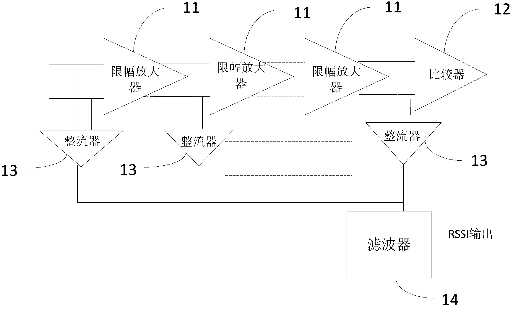
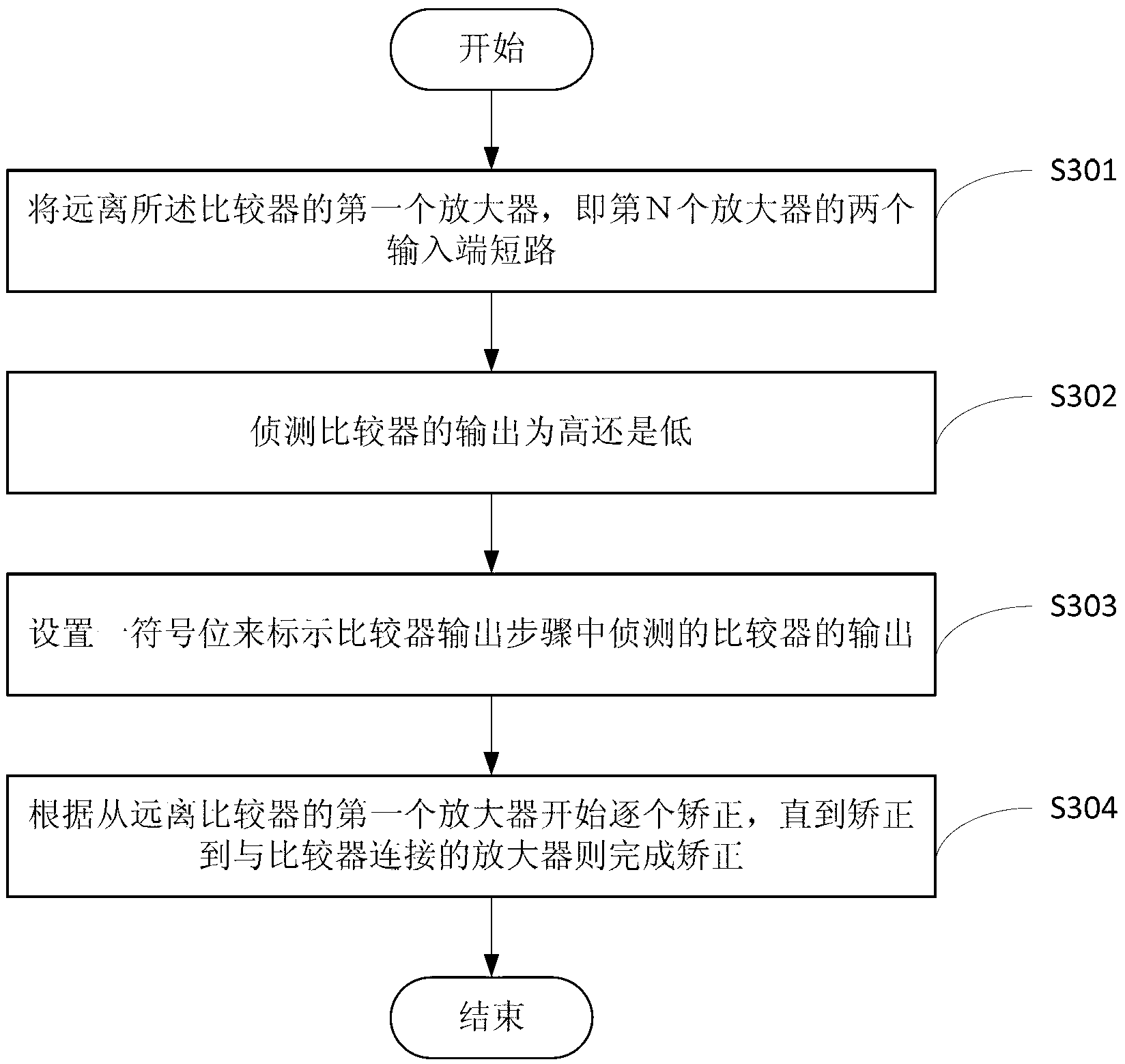
[0025] RSSI circuit block diagram of the present invention and figure 1 The prior art shown is the same. The specific method for correcting the deviation of the circuit is as follows: image 3 shown.

[0026] Step S301, the step of short-circuiting the input terminals: short-circuiting the first-stage amplifier 11 away from the comparator 12, that is, the two input terminals of the first-stage amplifier 11;

[0027] Step S302, comparator output detection step: detecting whether the output of the comparator 12 is high level or low level;

[0028] Step S303, sign bit setting step: set a sign bit to indicate the output of the comparator 12 detected in the comparator 12 outp...


PUM


Abstract

The invention relates to a received signal strength indicator circuit and a method for correcting deviation thereof. The method includes a step for enabling input ends to be in short circuit: enabling the two input ends of a first-stage amplifier which is far away from a comparator to be in short circuit; a step for detecting output of the comparator: detecting whether the output of the comparator is a high level or a low level; a step for correcting the deviation: starting to correct amplifiers from the first-stage amplifier which is far away from the comparator to a last-stage amplifier which is connected with the comparator one by one. When each amplifier is corrected, the currently adjusted amplifier provides a correction voltage which is opposite to the output of the comparator, then current output of the comparator is detected, the voltage provided by the currently adjusted amplifier is blocked when the current output of the comparator is opposite to the output detected in the step for detecting the output of the comparator, and the voltage provided by the currently adjusted amplifier is maintained when the current output of the comparator is identical to the output detected in the step for detecting the output of the comparator.

Description

technical field [0001] The invention relates to a receiving signal strength indicating circuit, in particular to a receiving signal strength indicating circuit capable of correcting signal deviation and a correction method for signal deviation. Background technique [0002] A receiver signal strength indicator (received signal strength indicator, RSSI) circuit 10 such as figure 1 Shown, comprise a plurality of limiting amplifiers 11 connected in series, a plurality of limiting amplifiers 11 connected in series connects a comparator 12 to output comparison signal, the input end and the output end of each limiting amplifier 11 all connect a rectifier 13, the rectifier 13 The input AC signal can be converted into a DC signal, and all the rectifiers 13 are connected to a filter 14, and the converted DC signal is filtered by the filter 14 to output an RSSI signal. [0003] For example, the RSSI circuit 1 includes 11 stages of limiting amplifiers 11, each stage can amplify the si...

Claims


Application Information

Patent Timeline
Patent Type & Authority Applications(China)
IPC IPC(8): H04B1/16H04B1/12
Inventor 陈磊
Owner WUXI ZETAI MICROELECTRONICS
Why Eureka
Try Eureka