
Automatic dismantling and separating device for waste dry cell and dismantling and separating method

A separation device, dry battery technology, applied in battery recycling, solid waste removal, recycling technology and other directions, can solve the problems of dismantling hazards, low manual dismantling efficiency, inability to meet large-scale dismantling, separation and recycling, etc. High degree of automation, improve work efficiency and separation effect, and solve the effect of incomplete separation

Inactive Publication Date: 2013-09-11
ANHUI UNIV OF SCI & TECH
View PDF8 Cites 21 Cited by
  • Summary
  • Abstract
  • Description
  • Claims
  • Application Information

AI Technical Summary

Problems solved by technology

[0003] At present, the dismantling and separation process and device of waste dry batteries mainly adopt manual dismantling and mechanical crushing. This method has the following disadvantages:) Manual dismantling of batteries can realize the classification of paste electrolyte, zinc cylinder and carbon rod in dry batteries Recycling, but there are potential hazards in the dismantling process, and the efficiency of manual dismantling is low. An average of 5 minutes per battery cannot meet the requirements of large-scale dismantling, separation and recycling; 2) The mechanical crushing method is to squeeze and cut waste dry batteries as a whole , high efficiency, but the paste electrolyte, zinc cylinder and carbon rods available in dry batteries are mixed together during dismantling, and the mixture cannot be sorted and recycled quickly and accurately

Method used


Image

  • Automatic dismantling and separating device for waste dry cell and dismantling and separating method
  • Automatic dismantling and separating device for waste dry cell and dismantling and separating method

Examples


Embodiment Construction

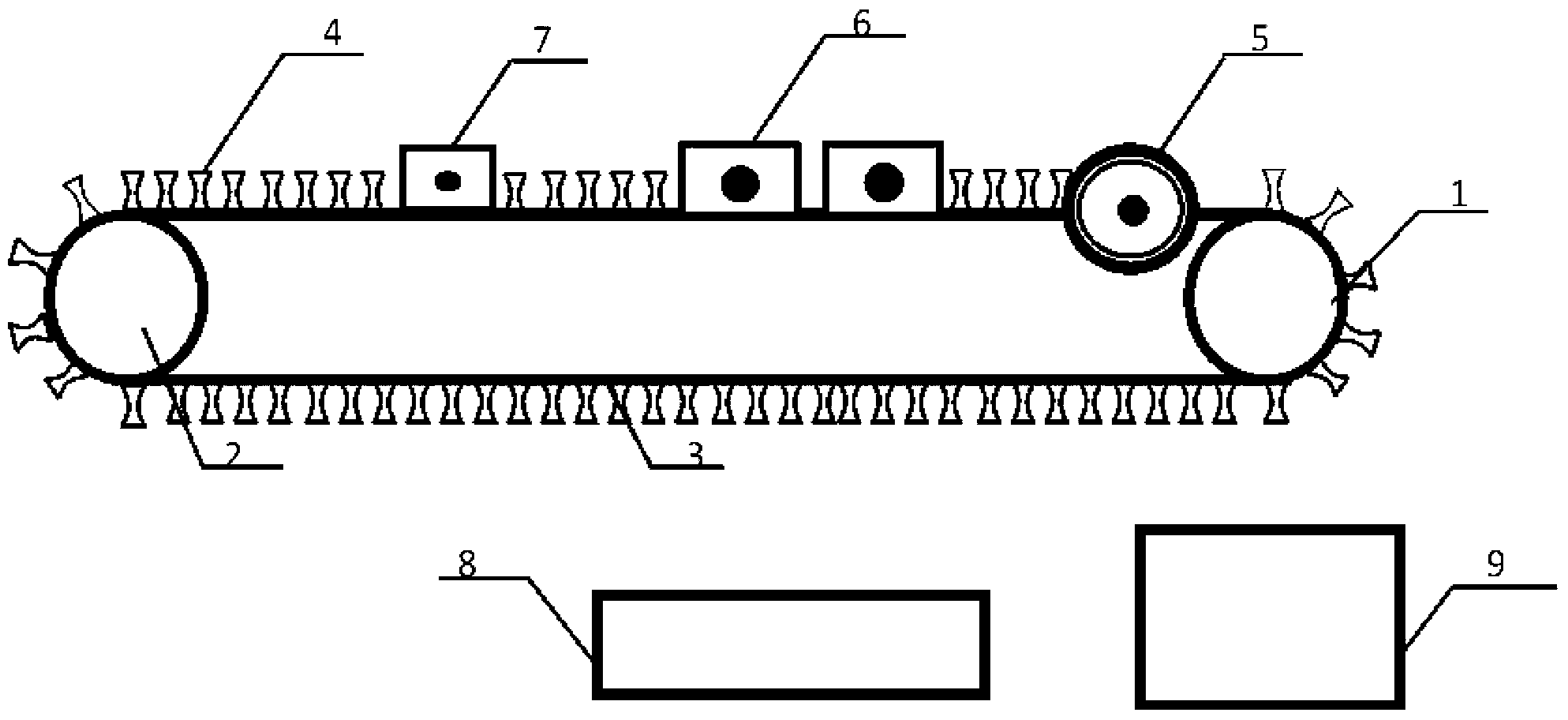
[0031] See attached Figure 1 ~ Figure 2 The automatic dismantling and separation device for waste dry batteries includes two rollers, a conveyor belt 3, a grinding wheel set 5, a striker 6, a cutter 7 and a vibrating screen 8; the surface of the conveyor belt 3 is provided with a plurality of rubber partitions evenly spaced 4. The two rollers include a first roller 1 and a second roller 2, wherein the first roller 1 is a driving roller for driving the conveyor belt 3 to move, and the second roller 2 is a driven roller; the grinding wheel set is arranged on On the conveyor belt 3 and located at one end close to the first drum 1, the grinding wheel set 5 includes a first grinding wheel and a second grinding wheel, and the first grinding wheel and the second grinding wheel are respectively located on both sides of the conveyor belt 3; On the first side of the conveyor belt 3, a cutter 7 is arranged on the conveyor belt 3 and at an end close to the second drum 2; The striker 6 i...


PUM


Abstract

The invention discloses an automatic dismantling and separating device for a waste dry cell and a dismantling and separating method, The automatic dismantling and separating device comprises a roller, a belt, a grinding wheel group, a firing pin, a cutter and a vibrating screen, wherein the conveyor belt is provided with a plurality of rubber partition plates; the grinding wheel group is arranged on the conveyor belt; the first side of the conveyor belt is provided with the cutter and the firing pin; the second side of the conveyor belt is provided with the vibrating screen. A first roller, a grinding wheel, the cutter and the firing pin are powered on; the waste dry cells are fixedly arranged between two adjacent partition plates of the belt one by one. Along with the movement of the belt, two ends of each waste dry cell are cut off by the grinding wheel rotating at high speed, paste and a carbon bar of the dry cell are pushed out of a shell of the dry cell through the firing pin, and a zinc skin is separated from a plastic skin through the cutter. The automatic dismantling and separating device and dismantling and separating method for the waste dry cell have the advantages that a paste electrolyte, a zinc drum and the carbon bar can be comprehensively recycled, and the processing working efficiency and a separation effect of the waste dry cell can be improved.

Description

technical field [0001] The invention relates to a battery waste treatment and decomposition device, in particular to a waste dry battery automatic disassembly and separation device and a disassembly and separation method for recycling waste dry batteries. Background technique [0002] With the rapid growth of dry battery production and consumption, dry batteries have brought great convenience to people's lives, and at the same time, the environmental hazards of waste dry batteries have always been one of the issues of great concern to the public. Using effective technology and equipment to dismantle waste dry batteries, and comprehensively recycle the paste electrolyte, zinc cylinder and carbon rods obtained from dismantling, is an effective way to solve the pollution caused by waste dry batteries to the environment and realize the comprehensive recycling of resources. . [0003] At present, the dismantling and separation process and device of waste dry batteries mainly ado...

Claims


Application Information

Patent Timeline
Patent Type & Authority Applications(China)
IPC IPC(8): H01M6/52B09B3/00
CPCY02W30/84
Inventor 刘银于冲黄关火闵凡飞朱金波张明旭
Owner ANHUI UNIV OF SCI & TECH
Learn More