
Compression fatigue testing device and method for low-speed impacted composite material laminate

A low-speed impact and fatigue test technology, applied in the field of fatigue test, can solve the problem of direct application of composite laminate test pieces to compression fatigue test, etc., and achieve good neutrality effect.

Inactive Publication Date: 2013-09-11
BEIHANG UNIV
View PDF4 Cites 17 Cited by
  • Summary
  • Abstract
  • Description
  • Claims
  • Application Information

AI Technical Summary

Problems solved by technology

[0004] The technical solution of the present invention is to overcome the deficiency in the prior art that the composite material laminated plate specimen after the low-velocity impact test cannot be directly applied to the compression fatigue test, and provide a compression fatigue test device and method for the composite material laminated plate after the low-velocity impact , which solves the problem of fixing the specimen in the compression fatigue test of the composite laminate with initial low-velocity impact damage, so that the composite laminate does not need to be cut after the low-velocity impact test, and can be directly used in the compression fatigue test. In the fatigue test, the specimen It can only move along the direction of the compressive load under 1 degree of freedom, which avoids the wear of the test piece in the fatigue test, and also solves the problem of the neutrality of the test piece under the compressive load, greatly reducing the compression Possibility of instability during fatigue testing

Method used


Image

  • Compression fatigue testing device and method for low-speed impacted composite material laminate
  • Compression fatigue testing device and method for low-speed impacted composite material laminate
  • Compression fatigue testing device and method for low-speed impacted composite material laminate

Examples


Embodiment Construction

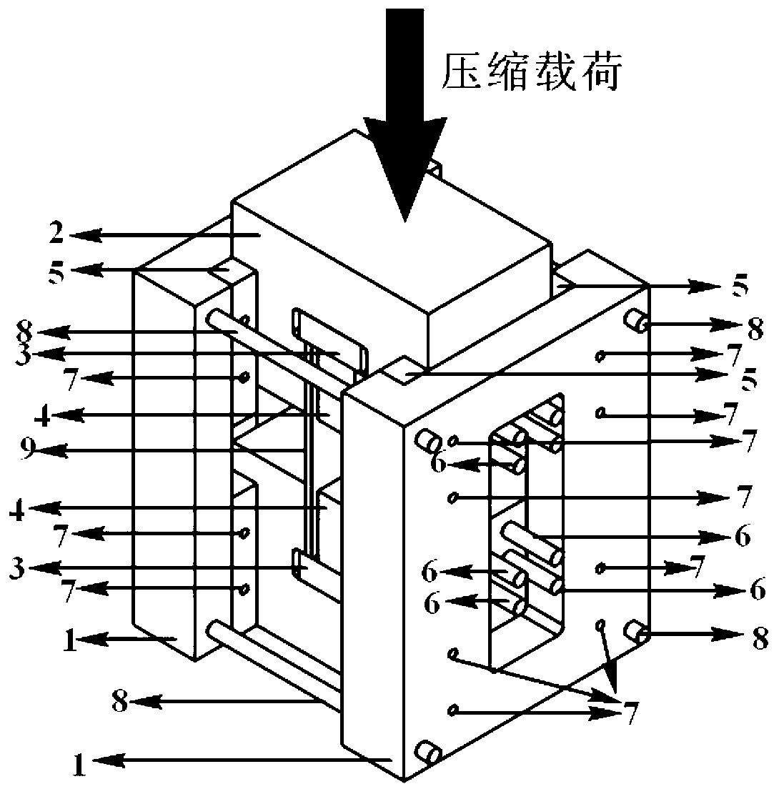
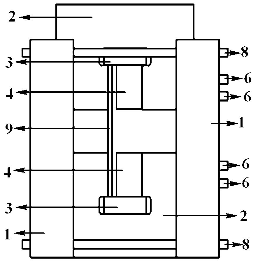
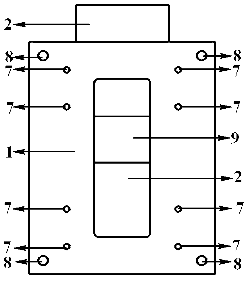
[0047] The compression fatigue test device for composite laminates with initial low-velocity impact damage provided by the present invention will be further described in detail below in conjunction with the accompanying drawings.

[0048] Such as figure 1 , 2 , 3 and 4, the present invention includes two guiding units 1, two loading units 2, two transfer units 3, two fixing units 4, eight slide rail units 5, eight bolt tightening units 6, ten Six bolt connection units 7 and four screw connection units 8 . Each guide unit 1 needs to be connected with four slide rail units 5 through the bolt connection unit 7, and the two guide units 1 hug the two loading units 2 through four screw connection units 8, and the two loading units 2 have T-shaped hole slots One side of the two loading units needs to face inward and correspond to each other, and ensure that the side with the bolt holes of the two loading units faces one direction, each loading unit 2 contains a transfer unit 3 and ...


PUM


Abstract

The invention discloses a compression fatigue testing device and method for a low-speed impacted composite material laminate. The device comprises two guide units, two load units, two transmission units, two fixing units, eight sliding rail units, eight bolt tightening units, sixteen bolt connecting units and four screw rod connecting units. The problem that a test piece cannot be fixed in a compression fatigue test of the composite material laminate with initial low-speed impact damage is solved, so that the test piece is not required to be cut after the low-speed impact test and can be directly applied to the compression fatigue test, and the centering property of the test piece is guaranteed while the test piece is fixed through certain parts provided according to the invention.

Description

technical field [0001] The invention belongs to the field of fatigue tests, in particular to a compression fatigue test device and method for composite material laminated plates after low-speed impact. Background technique [0002] Composite laminates have become one of the indispensable materials in the field of modern aerospace due to their advantages such as high specific strength, high specific stiffness, and strong designability. Sensitive, especially after low-velocity impact, the surface of the laminate can hardly be seen to be damaged, but the interior will produce large-area matrix cracking and interlayer delamination. However, under compressive fatigue loads, these damages can be induced and coupled with each other, and the damage evolution and failure mechanism are very complex. At present, with the wide application of composite materials in the main load-bearing structures of aircraft, the term "static coverage fatigue" is no longer suitable for practical requir...

Claims


Application Information

Patent Timeline
IPC IPC(8): G01N3/08
Inventor 张建宇李明赵丽滨时新红陈玉丽
Owner BEIHANG UNIV
Learn More